Device and method for alleviation of pain

a technology for pain relief and devices, applied in medical science, surgery, diagnostics, etc., can solve the problems of thermal damage to and/or prolonged retraction of sensitive anatomic structures, and the methods of using such devices are often limited exclusively

Inactive Publication Date: 2015-12-17
HEGGENESS MICHAEL
View PDF18 Cites 30 Cited by
  • Summary
  • Abstract
  • Description
  • Claims
  • Application Information

AI Technical Summary

Benefits of technology

[0016]According to one aspect of the present invention, a target-treating system is provided. The system is configured to treat a target disposed within a bone of a patient. The system comprises a probe configured to be inserted into the bone and navigated therethrough toward the target. The probe comprises a shaft that includes a proximal end, a distal end, and a main body extending between and interconnecting the proximal end and the distal end. The distal end is configured to engage the target such that, upon activation of the probe, the target is treated. The main body includes an obstruction-avoidance portion configured such that incidental damage to a sensitive biological structure by the shaft is at least in part avoided. The obstruction-avoidance portion includes a proximal section, a distal section at least in part transversely offset relative to the proximal section, and an intermediate section extending between and interconnecting the proximal and distal sections. The proximal section and the intermediate section define a proximal bend. The intermediate section and the distal section define a distal bend oriented such that the proximal bend and the distal bend are generally oppositely oriented.

Problems solved by technology

Those of ordinary skill in the art will appreciate that devices and methods for alleviating pain often result in thermal damage to and / or prolonged retraction of sensitive anatomic structures near or adjacent to the pain source itself and / or the access route to the pain source.
Furthermore, methods of use of such devices are often limited exclusively to generally posterior approaches (i.e., entry from the posterior side) to the pain source due at least in part to obstructed generally anterior access.

Method used


Image

  • Device and method for alleviation of pain
  • Device and method for alleviation of pain
  • Device and method for alleviation of pain

Examples


Embodiment Construction

[0044]The present invention is susceptible of embodiment in many different forms. While the drawings illustrate, and the specification describes, certain preferred embodiments of the invention, it is to be understood that such disclosure is by way of example only. There is no intent to limit the principles of the present invention to the particular disclosed embodiments.

[0045]It is further noted that preferred embodiments of the present invention may in some instances be realized through a combination of features compatible for use together despite having been presented independently as part of separate embodiments in the below description and drawings.

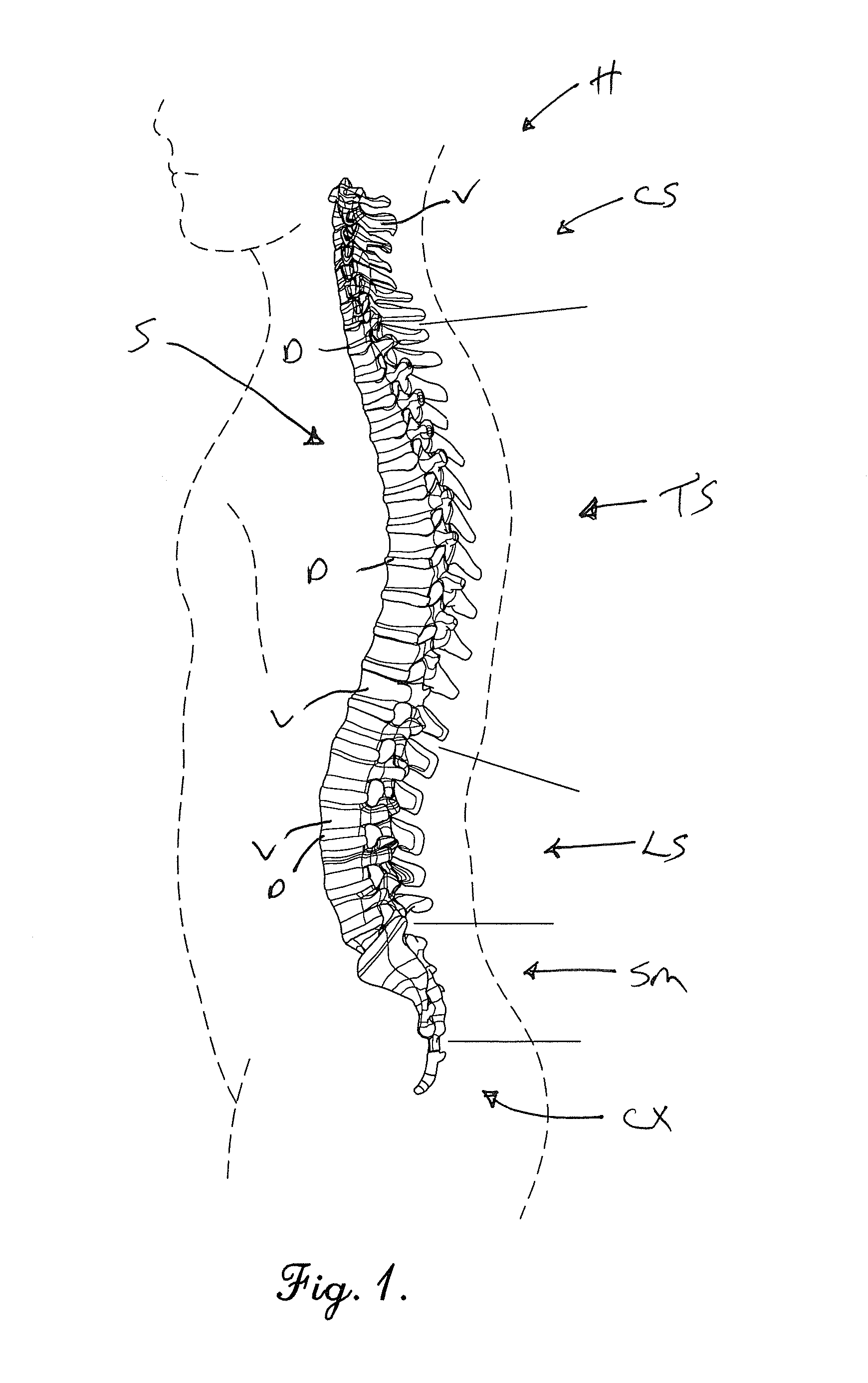
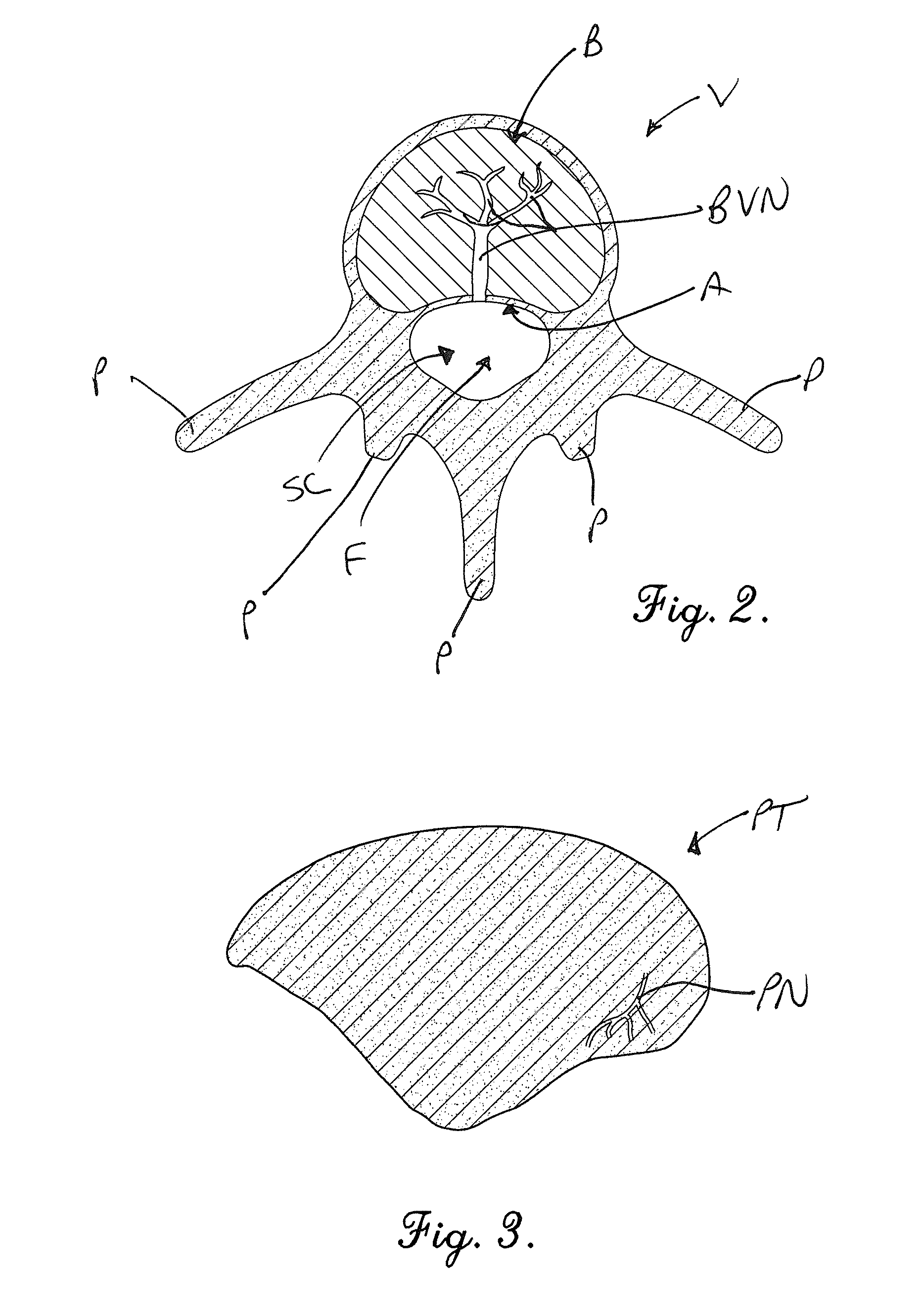
[0046]Yet further, it is noted that relevant directional references (e.g., anterior, posterior, proximal, and distal, etc.) used herein should be understood in the context of standard anatomical orientation. Such directional references will be readily understood by those of ordinary skill in the art.

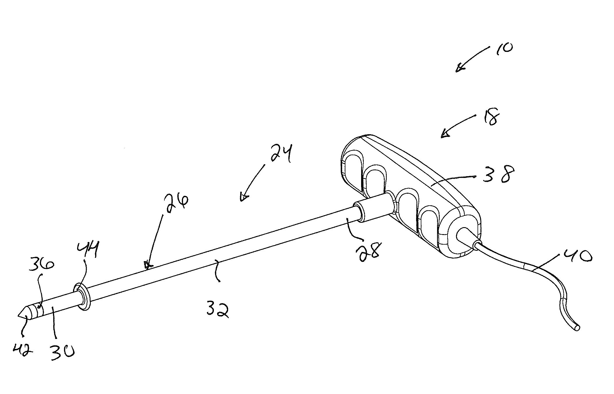
[0047]A first preferred target-trea...


PUM


Abstract

A target-treating system treats a target disposed within a bone of a patient. The system comprises a probe configured to be inserted into the bone and navigated therethrough toward the target. The probe comprises a shaft that includes a proximal end, a distal end, and a main body extending between and interconnecting the proximal end and the distal end. The distal end is configured to engage the target such that, upon activation of the probe, the target is treated.

Description

CROSS-REFERENCE TO RELATED APPLICATION[0001]The present application claims priority from U.S. Provisional Patent Application No. 62 / 012,091, filed Jun. 13, 2014, the entire disclosure of which is hereby incorporated by reference herein. Furthermore, the present application is related to U.S. Pat. No. 6,699,242, filed Feb. 1, 2001, and U.S. Provisional Patent Application Ser. No. 60 / 179,959, filed Feb. 3, 2000, the entire disclosures of both of which are hereby incorporated by reference herein.BACKGROUND OF THE INVENTION[0002]1. Field of the Invention[0003]The present invention relates generally to a device and method for treatment of a target structure. The device and method are particularly well-suited for surgical ablation of pain-producing structures within a bone (e.g., intraosseus nerves). For instance, as will be discussed in greater detail below, preferred embodiments of the present invention are well suited for use with methods for the treatment of back pain. More particular...

Claims


Application Information

Patent Timeline
Patent Type & Authority Applications(United States)
IPC IPC(8): A61B18/14
CPCA61B18/148A61B18/1477A61B2018/00577A61B2018/1405A61B2018/1425A61B2018/1432A61B2018/00434A61B2018/00791A61B2090/036
Inventor HEGGENESS, MICHAEL
Owner HEGGENESS MICHAEL
Why Eureka
Try Eureka