Pneumatic tire

a technology of pneumatic tires and grooves, which is applied in the direction of non-skid devices, vehicle components, transportation and packaging, etc., can solve the problems of difficult movement of small stones in the groove, difficult swing of projections having triangular prisms,

Active Publication Date: 2015-12-17
TOYO TIRE & RUBBER CO LTD
View PDF2 Cites 11 Cited by
  • Summary
  • Abstract
  • Description
  • Claims
  • Application Information

AI Technical Summary

Benefits of technology

[0008]The present invention therefore provides a pneumatic tire in which small stones are less likely to be stuck in a groove and the small stones even if they are stuck in the groove can be rapidly ejected.

Problems solved by technology

However, once small stones are stuck between a side of the groove and a side of the projection, the projection having a triangular prism shape is difficult to swing, since the thus stuck small stones do not press the upper part of the projection.
Therefore, the stuck small stones are difficult to move in the groove, and may remain stuck without being ejected from the groove in some cases.
The small stones remaining stuck in the groove as above are not preferable because the small stones cause damage to the tread such as cracks in blocks by pressing the blocks.

Method used


Image

  • Pneumatic tire
  • Pneumatic tire
  • Pneumatic tire

Examples


Embodiment Construction

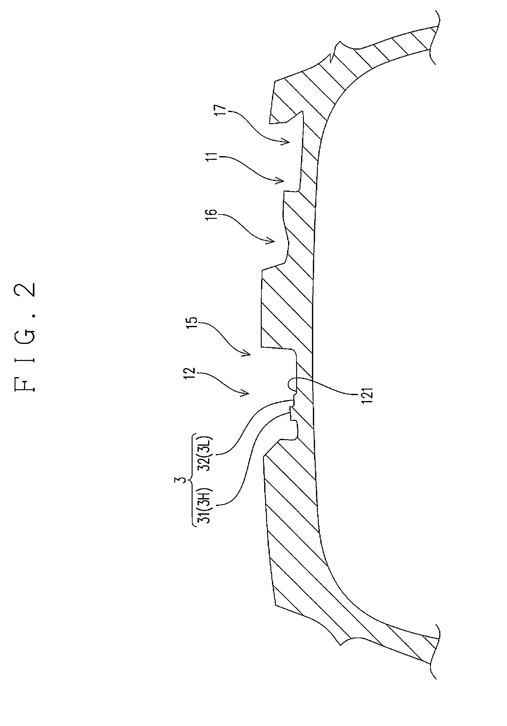
[0026]Next, a pneumatic tire according to an embodiment as an example of the present invention is described. In the following description about the “vertical” directions, the “lower” direction is the side closer to the groove bottom (radially inward direction of the tire), and the “upper” direction is the side farther from the groove bottom (radially outward direction of the tire). In particular, in order to indicate a vertical direction in the figure, the expression “the upper side in the figure” or “the lower side in the figure” is used.

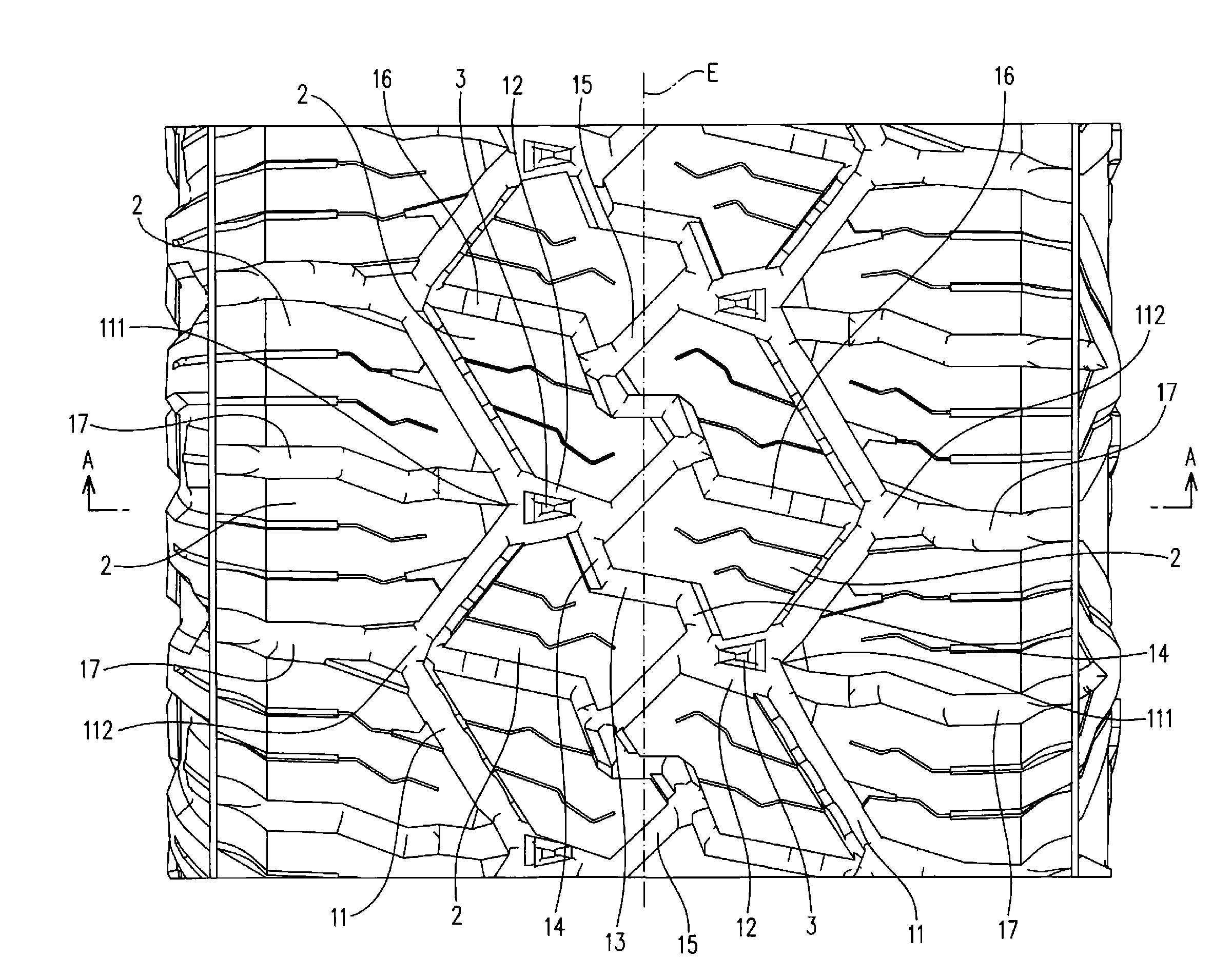
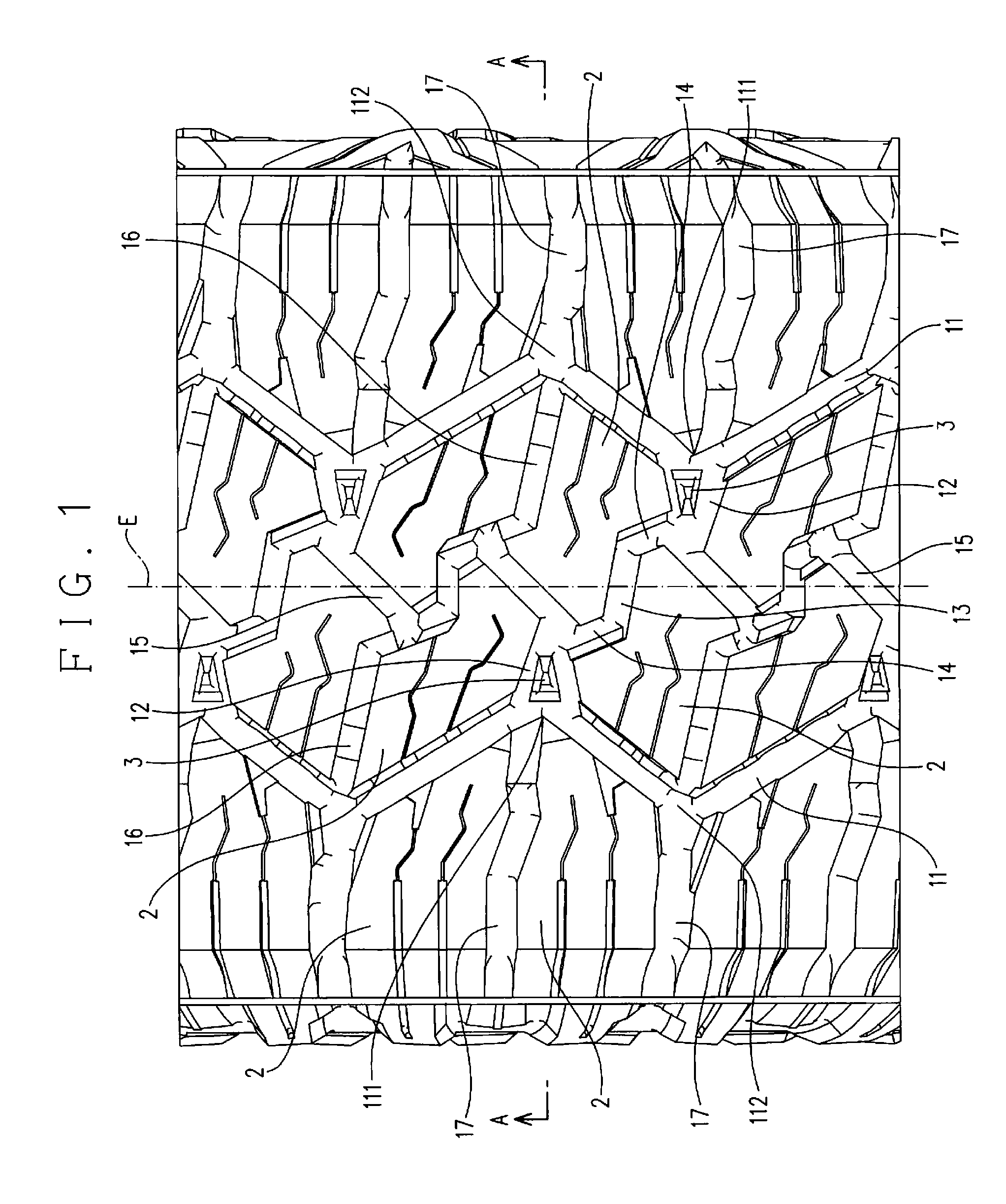
[0027]The tread pattern of the tire of this embodiment is a block pattern as shown in FIG. 1. On the tread of the tire, main grooves 11, transverse grooves 12, transverse groove-intermediating secondary transverse grooves 13, auxiliary grooves 14, circumferential secondary grooves 15, intermediate secondary transverse grooves 16, and shoulder transverse grooves 17 are formed. Each groove has a groove bottom and groove side surfaces arising from the...


PUM


Abstract

The present invention provides a pneumatic tire including: a groove formed in a tread, the groove having a groove bottom and groove side surfaces arising from the groove bottom; and a projection projecting from the groove bottom, wherein the projection includes a low-step portion located at a low position with reference to the groove bottom and a high-step portion located at a high position with reference to the groove bottom, the low-step portion has a first-side inclined surface inclined in a depth direction of the groove along a first groove side surface of the groove and a second-side inclined surface inclined in the depth direction of the groove along a second groove side surface of the groove, and the first-side inclined surface and the second-side inclined surface are inclined in different directions from each other.

Description

CROSS-REFERENCE TO RELATED APPLICATION[0001]This application claims the benefit of Japanese Patent Application No. 2014-122509, filed on Jun. 13, 2014, which is incorporated herein by reference.BACKGROUND OF THE INVENTION[0002]1. Field of the Invention[0003]The present invention relates to a pneumatic tire in which a projection for suppressing stone sticking is formed.[0004]2. Background Art[0005]There is a pneumatic tire (hereinafter, referred to as “tire”) including a projection (called “stone ejector”) for suppressing stone sticking, that is, sticking of small stones in a groove formed in the tread. For example, a tire disclosed in JP H10-100616 A can be mentioned.[0006]The projection of the tire disclosed in JP H10-100616 A is a projection having a triangular prism shape projecting from a groove bottom. Small stones that have entered the groove in which the projection is formed during running of the tire are prevented from entering the inside of the groove by abutting the top su...

Claims


Application Information

Patent Timeline
Patent Type & Authority Applications(United States)
IPC IPC(8): B60C11/13
CPCB60C2011/1361B60C11/1353B60C11/047B60C11/11B60C2011/0346
Inventor KUWANO, SHINGO
Owner TOYO TIRE & RUBBER CO LTD
Why Eureka
Try Eureka