Manufacturing apparatus and manufacturing method for astigmatic spectacle lens

a manufacturing method and technology of astigmatic spectacles, applied in the field of manufacturing apparatus and astigmatic spectacle lens manufacturing, can solve the problems of loss of progressive power portion, loss of continuity in the surface shape constituted by the enlarged or reduced average dioptric power distribution or astigmatism distribution, and inability to substantially maintain optical continuity of both of the average dioptric power distribution

Inactive Publication Date: 2015-12-17
HOYA CORP
View PDF2 Cites 1 Cited by
  • Summary
  • Abstract
  • Description
  • Claims
  • Application Information

AI Technical Summary

Benefits of technology

[0007]According to the manufacturing apparatus of the embodiment of the invention, spectacle lenses in which the difference between addition effects actually acing on left and right eyes of a wearer on the principal meridian from the first refractive portion to the second refractive portion is reduced while ensuring the optical continuity and the continuity in a surface shape are manufactured. As a result, degrees of accommodation required for left and right eyes can be maintained at the same level, and in this case suitable binocular intermediate vision and near vision can be achieved. Furthermore, since, regarding the spectacle lenses thus manufactured, the difference between aberrations on the left and right visual lines is reduced, the quality of images formed on retinas of left and right eyes can be made equal to each other, and therefore a factor hampering the binocular vision function can be suppressed. As a result, suitable binocular vision can be guaranteed at every object distance from a long distance to a short distance, for example.
[0014]According to the manufacturing apparatus and the manufacturing method of the embodiment of the invention, since the difference between addition effects actually acing on left and right eyes of a wearer on the principal meridian from the first refractive portion to the second refractive portion is reduced while ensuring the optical continuity and the continuity in a surface shape and the difference between aberrations on the left and right visual lines is reduced, spectacle lenses capable of guaranteeing suitable binocular vision, for example, at every object distance from a long distance to a short distance are provided.

Problems solved by technology

However, when the enlarging rate or the reducing rate with respect to the average dioptric power distribution and the astigmatism distribution differs depending on directions, it becomes impossible to substantially maintain optical continuity of both of the average dioptric power distribution and the astigmatism distribution, and thereby, fir example, a portion in which the distribution changes rapidly appears locally.
When such a portion appears in the progressive power portion, problem arises that ‘continuity in a field of vision’ which is one of important factors for spectacle lenses having a progressive power portion is lost.
Furthermore, when the enlarging rate or the reducing rate with respect to the average dioptric power distribution and the astigmatism distribution differs depending on directions, a problem arises that continuity in a surface shape constituted by the enlarged or reduced average dioptric power distribution or astigmatism distribution is lost (a step appears on a lens surface),

Method used


Image

  • Manufacturing apparatus and manufacturing method for astigmatic spectacle lens
  • Manufacturing apparatus and manufacturing method for astigmatic spectacle lens
  • Manufacturing apparatus and manufacturing method for astigmatic spectacle lens

Examples


Embodiment Construction

[0027]In the following, a spectacle lens manufacturing system according to an embodiment of the invention is explained.

[0028]Spectacle Lens Manufacturing System 1

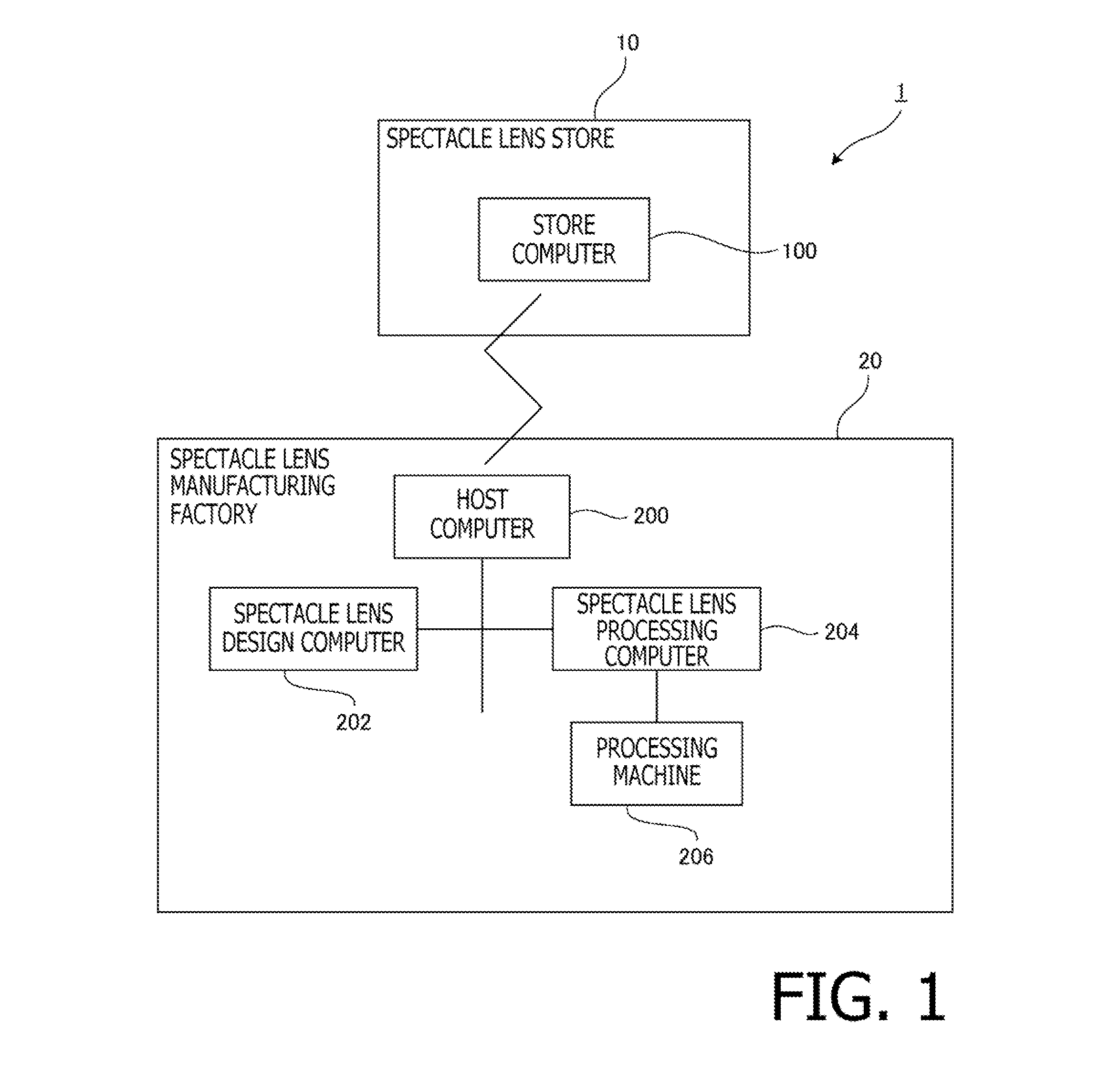
[0029]FIG. 1 is a block diagram illustrating a configuration of a spectacle lens manufacturing, system 1 according to the embodiment. As shown in FIG. 1, the spectacle lens manufacturing system 1 includes an optical store 10 which orders spectacle lenses according to a prescription for a customer (a wearer), and a spectacle lens manufacturing factory 20 which manufactures spectacle lenses after receiving the order from the optical store 10. The order to the spectacle lens manufacturing factory 20 is issued through a predetermined network, such as the Internet. or data transmission by, for example, facsimile. Orders may include ophthalmologis general consumers.

[0030]Optical Store 10

[0031]In the optical store 10, a store computer 100 is installed. The store computer 100 is, for example, a general PC (Personal Computer, and so...


PUM


Abstract

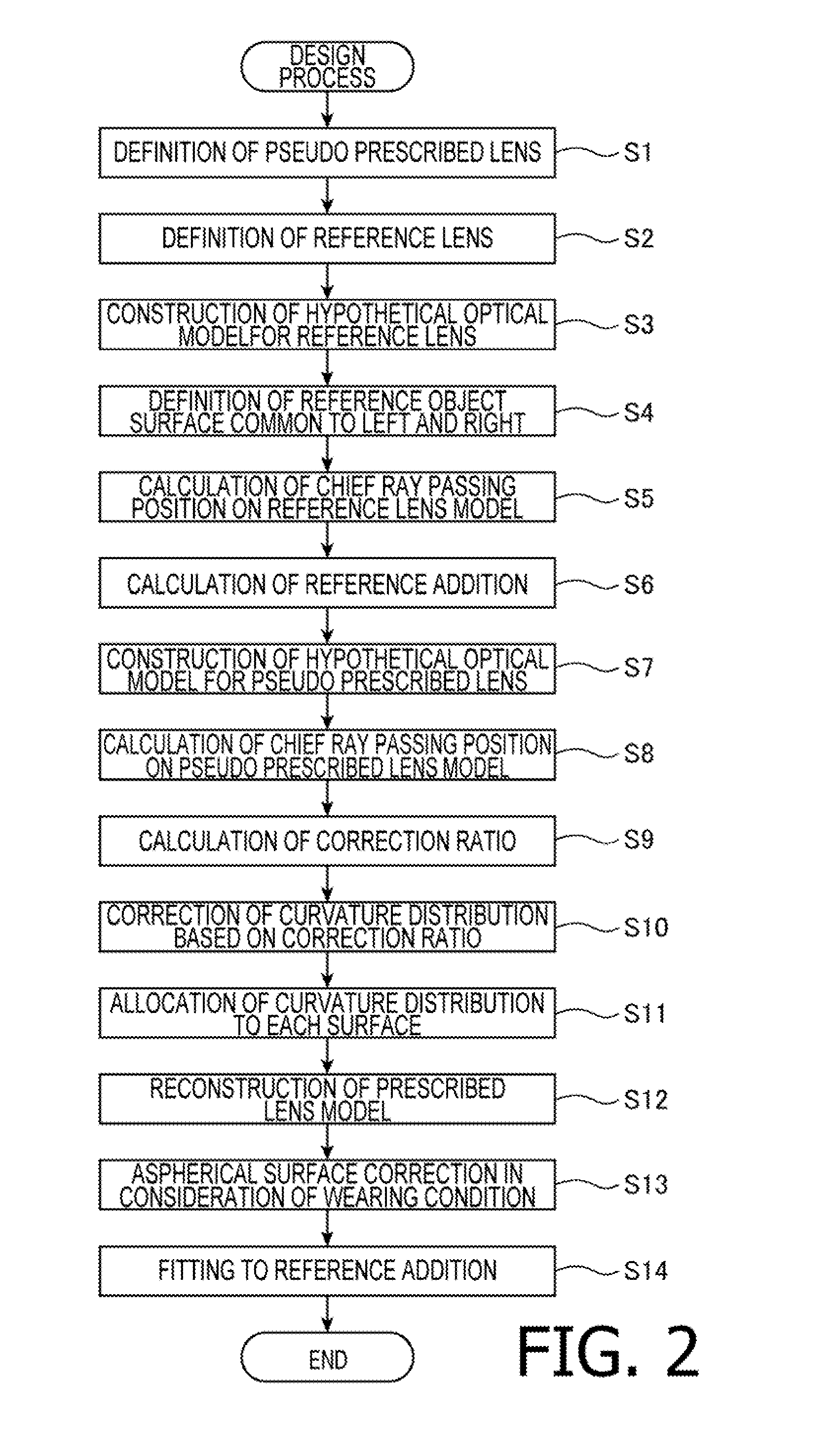
A reference lens common to left and right and reference object surface common to left and right including a plurality of object surfaces; calculating a ratio between distance from an intersection between a visual line in a front view and the reference lens to chief ray passing position on the reference lens and distance from an intersection between the visual line in the front view and the pseudo prescribed lens to the chief ray passing position on the pseudo prescribed lens; correcting, for each of the left and the right, a curvature distribution of pseudo prescribed lens' by correcting curvature at the chief ray passing position on the pseudo prescribed lens corresponding to each point on each of the plurality of object surfaces; and correcting, for each of the left and the right, curvature distribution of the prescribed lens based on the corrected curvature distribution of the pseudo prescribed lens.

Description

TECHNICAL FIELD[0001]The present invention relates to a manufacturing apparatus and a manufacturing method for an astigmatic spectacle lens comprising a first refractive portion having a first refractive power, a second refractive portion having a second refractive power stronger than the first refractive portion, and a progressive power portion in which the refractive power changes progressively from the first refractive power portion to the second refractive power portion.BACKGROUND ART[0002]A spectacle lens having a retractive power portion in which the refractive power changes progressively is known. For example, a distance-near progressive power lens is designed such that the dioptric power changes progressively on a principal meridian so that a wearer can see an object dearly and seamlessly from a long distance to a short distance. Many of spectacle lenses of this type are designed depending on prescribed individual dioptric powers for left and right eyes and a wearing conditi...

Claims


Application Information

Patent Timeline
Patent Type & Authority Applications(United States)
IPC IPC(8): G02C7/02G02C7/06
CPCG02C7/027G02C2202/06G02C7/068G02C7/025G02C7/028G02C7/063
Inventor KOZU, KAZUMA
Owner HOYA CORP
Why Eureka
Try Eureka