Gas storage cartridge

a technology of gas storage and gas storage cartridges, which is applied in the direction of liquid materials, transportation and packaging, packaging goods types, etc., can solve the problems of deteriorating methods, gas storage material not being uniformly and stably heated, and gas storage material efficiency deteriorating, so as to reduce the complexity and difficulty of assembling, the effect of gas storage material differen

Inactive Publication Date: 2012-06-28
ASIA PACIFIC FUEL CELL TECH
View PDF16 Cites 16 Cited by
  • Summary
  • Abstract
  • Description
  • Claims
  • Application Information

AI Technical Summary

Benefits of technology

[0007]A second object of the present invention provides a simplified gas storage canister. After the modular gas storage cartridges are successively stacked over each other and accommodated within the inner space of the gas storage canister, the gas storage canister is assembled without difficulty.
[0008]A third object of the present invention provides a gas storage cartridge which is easily assembled and stably positioned. After several modular gas storage cartridges are successively stacked over each other and accommodated within the inner space of the gas storage canister, these gas storage cartridges are aligned with each other and positioned by simple positioning elements or positioning structures.
[0009]A fourth object of the present invention provides a gas storage cartridge with a compartment structure. The compartment structure is accommodated within the modular gas storage cartridge and has a plurality of compartments for storing a predetermined amount of gas storage material. Consequently, the gas storage material can be optimally distributed and uniformly heated, and the structural strength of the gas storage cartridge is enhanced.
[0010]A fifth object of the present invention provides a gas storage cartridge with a gap. Due to the gap between the top and inner peripheries of the gas storage cartridge, the possibility of resulting in deformation of the partition articles will be minimized.
[0013]By means of the present technology, the gas storage canister can be easily assembled by successively accommodating the stacked gas storage cartridges within the canister body without the need of using the complicated assembling process. Since the gas storage material has been precisely and previously filled into each modular gas storage cartridge, the difference of gas storage material between any two different filling processes will be largely reduced, the assembling complexity and difficulty will be reduced, and the possibility of resulting in deformation will be minimized. By using the gas storage canister of the present invention, each modular gas storage cartridge is uniformly and stably heated. Consequently, the efficiency of charging or releasing the gas (e.g. the hydrogen gas) is enhanced. Since there is a buffering space between any two adjacent stacked gas storage cartridges, even if the gas storage material is suffered from thermal expansion, the deformation of the canister body will be minimized. Consequently, the safety of operating the canister body is enhanced.
[0014]In the modular gas storage cartridge of the present invention, a predetermined amount of gas storage material is accommodated within the compartment of the compartment structure, so that the gas storage material is locally distributed. Consequently, during operation of the fuel cell system, the gas storage canister allows the external heat to be uniformly conducted to the compartments of all compartment structures. Since the heat applied to the inner portion and the outer portion of the gas storage material are not obviously distinguished during the heating stage, the released gas can be outputted more uniformly and stably. Under this circumstance, the operating efficacy of the present invention is enhanced. Moreover, since the compartment structure is accommodated within the receptacle of the gas storage cartridge and the partition plate is effective to reinforce the structural strength of the gas storage cartridge, the operation of the gas storage canister is more stable, and the working efficiency of the fuel cell system is enhanced. In such way, the gas storage cartridge is modularized to facilitate production, assembly and application, so that the industrial utilization is enhanced.

Problems solved by technology

Since the gas storage material is usually in a powdery form and the gas storage material is accommodated within a single receptacle of the canister body, if the volume of the gas storage material is too large, the gas storage material fails to be uniformly and stably heated.
Under this circumstance, the efficiency of releasing the gas (e.g. the hydrogen gas) from the gas storage material is deteriorated.
Unfortunately, these methods are unsatisfied because the thermal expansion of the gas storage material may result in deformation of the partition articles.
Under this circumstance, the gas storage material may be leaked to and stacked over other partition layers or a non-uniform heating problem may occur, so that the performance of the gas storage canister is impaired.
Moreover, it is inconvenient to fill the gas storage material into the gas storage canister because a special jig tool is indispensable.
The process of filling the gas storage material is complicated, and needs to be performed by a professional technician.
In addition, a difference of gas storage material between any two different filling processes is easily generated.
Under this circumstance, the operating performance of the gas storage canister is adversely affected.

Method used


Image

  • Gas storage cartridge
  • Gas storage cartridge
  • Gas storage cartridge

Examples


first embodiment

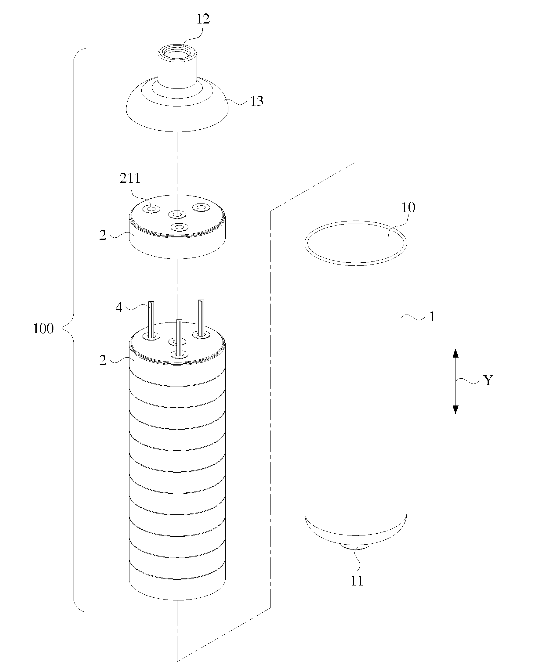
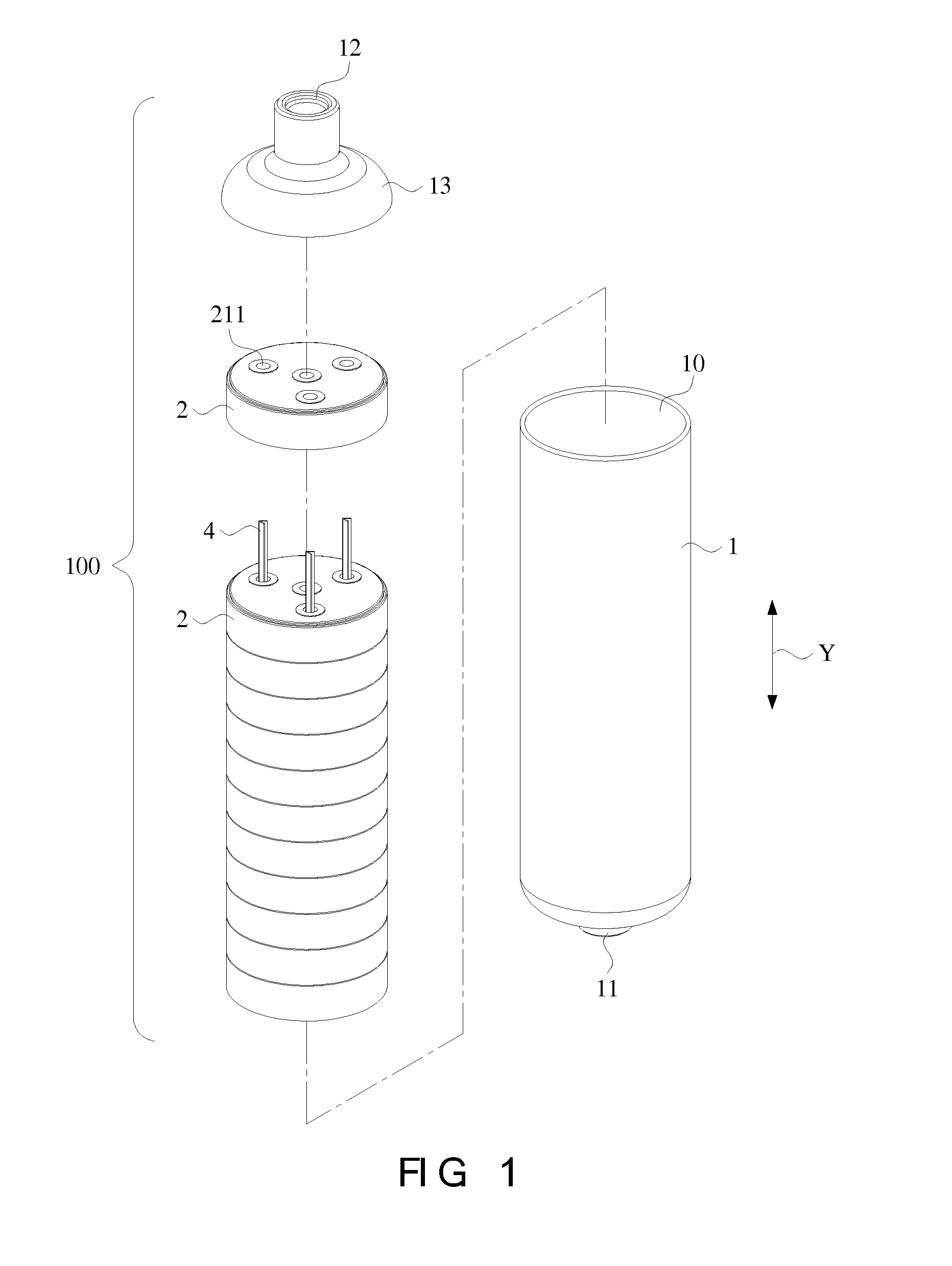
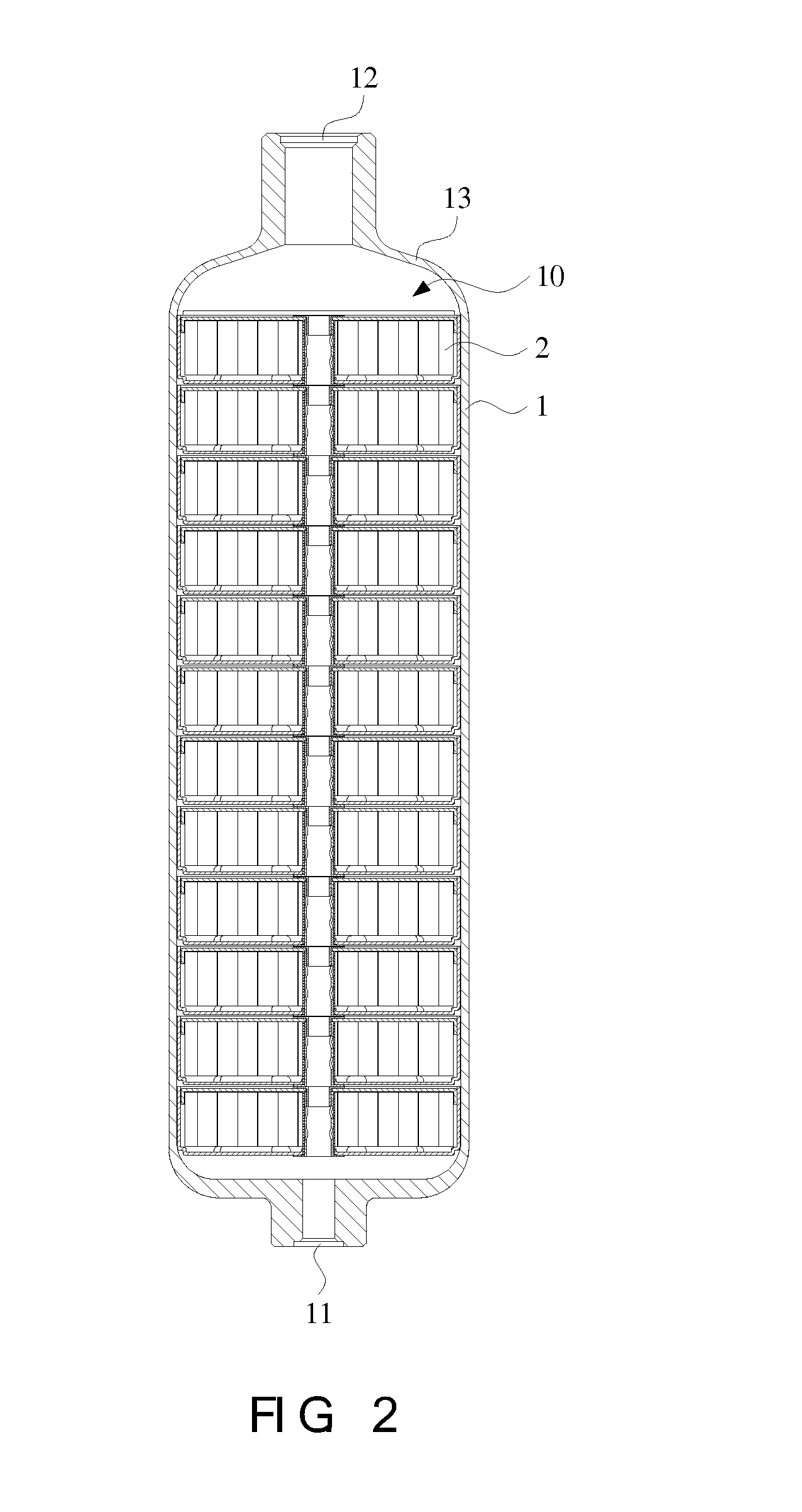
[0027]FIG. 3 is a schematic exploded view illustrating a gas storage cartridge of the gas storage canister according to the present invention. As shown in FIG. 3, the gas storage cartridge 2 comprises a first slab 21, a peripheral wall 22, and a second slab 23. The first slab 21, the peripheral wall 22 and the second slab 23 are collectively defined as a sealed cartridge unit with a receptacle. The shape of the gas storage cartridge is dependent on the shape of the canister body 1. The peripheral wall 22 is vertically extended from a periphery of the first slab 21 along the long axis direction Y. The second slab 23 is disposed on the top portion of the peripheral wall 22. In an embodiment, the second slab 23 (e.g. a flat slab or a lid plate with an edge) is accommodated within the top and inner periphery of the peripheral wall 22. Consequently, a receptacle P is defined by the gas storage cartridge 2 for accommodating the gas storage material. A plurality of ribs 212 are formed on t...

third embodiment

[0036]FIG. 8 is a schematic exploded view illustrating a gas storage cartridge according to the present invention. In comparison with FIG. 3, the first connecting part 31 is directly formed on the first slab 21. The filtering layer 34 is sheathed around the tube wall of the first connecting part 31. In addition, the second connecting part 33 is directly formed on the second slab 23, and aligned with the first connecting part 31. The configurations of other components of the gas storage cartridge 2b of this embodiment are similar to those of FIG. 3, and are not redundantly described herein.

fourth embodiment

[0037]FIG. 9 is a schematic exploded view illustrating a gas storage cartridge according to the present invention. In comparison with FIG. 8, the first connecting part 31 is directly formed on the second slab 23. The filtering layer 34 (or a filtering tube) is sheathed around the tube wall of the first connecting part 31. In addition, the second connecting part 33 is directly formed on the first slab 21, and aligned with the first connecting part 31. The configurations of other components of the gas storage cartridge 2c of this embodiment are similar to those of FIG. 8, and are not redundantly described herein.


PUM

PropertyMeasurementUnit
chemical energyaaaaaaaaaa
energyaaaaaaaaaa
volumeaaaaaaaaaa

Abstract

A gas storage cartridge includes a sealed cartridge unit for storing a gas storage material. The gas storage cartridge is defined by a first slab, a peripheral wall, and a second slab. At least one gas-guiding channel is accommodated within a receptacle of the gas storage cartridge. The first slab has a first gas inlet / outlet port and the second slab has a second gas inlet / outlet port aligned with the gas-guiding channel. Consequently, a gas is guided into the receptacle through the gas-guiding channel to be adsorbed by the gas storage material within the receptacle of the gas storage cartridge. Alternatively, the gas released from the gas storage material can be guided to the first gas inlet / outlet port and the second gas inlet / outlet port through the gas-guiding channel.

Description

FIELD OF THE INVENTION[0001]The present invention relates to a gas storage cartridge of a gas storage canister, and more particularly to a modular gas storage cartridge, which a plurality of gas storage cartridges are stacked over each other and accommodated within a gas storage canister.BACKGROUND OF THE INVENTION[0002]A fuel cell is a device that converts the chemical energy from a hydrogen-containing fuel into electricity through a chemical reaction with air. Consequently, the fuel cell is categorized as a new energy source. The hydrogen-containing fuel used in the fuel cell includes any type of hydrocarbon such as natural gas, methanol, ethanol (alcohol), product from water hydrolysis, marsh gas, or the like.[0003]The hydrogen gas is usually filled into a gas storage canister with metal hydride, so that the hydrogen gas is adsorbed and stored by the metal hydride. For using the hydrogen gas, the gas storage canister should be properly heated to release the hydrogen gas to the ap...

Claims


Application Information

Patent Timeline
Patent Type & Authority Applications(United States)
IPC IPC(8): B65D85/00
CPCF17C11/005F17C11/00
Inventor YANG, JEFFERSON YSLIAO, CHENG-HAMHSIAO, FENG-HSIANGKUO, TZU-WEI
Owner ASIA PACIFIC FUEL CELL TECH
Why Eureka
Try Eureka