

Manufacturing apparatus and manufacturing method for spectacle lens
a manufacturing method and spectacle lens technology, applied in the field of spectacle lens manufacturing method, can solve the problems of deteriorating the aberration of both eyes, hampering the development of suitable binocular vision, and unsuitable conventional lens design
- Summary
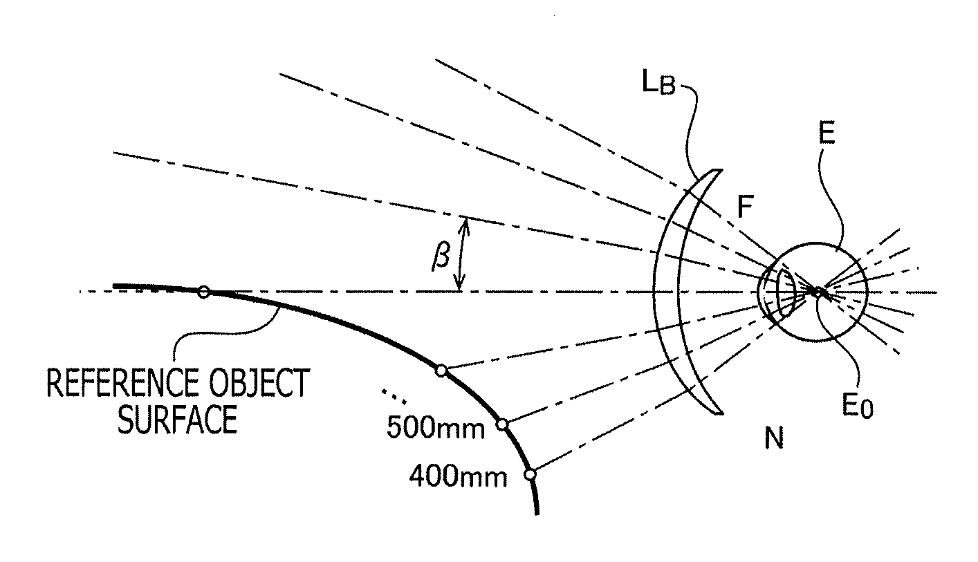
- Abstract
- Description
- Claims
- Application Information
AI Technical Summary
Benefits of technology
Problems solved by technology
Method used
Image

Examples
Embodiment Construction
[0027]In the following, a spectacle lens manufacturing system according to an embodiment of the invention is explained.
[0028]Spectacle Lens Manufacturing System 1
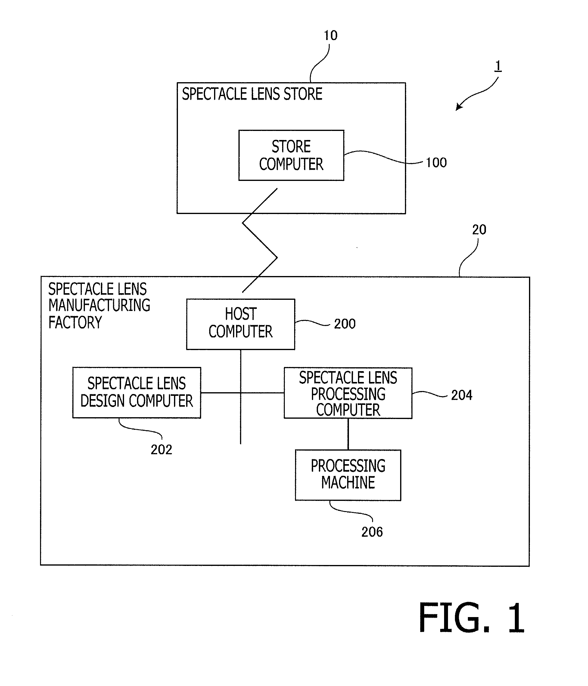
[0029]FIG. 1 is a block diagram illustrating a configuration of a spectacle lens manufacturing system 1 according to the embodiment. As shown in FIG. 1, the spectacle lens manufacturing system 1 includes an optical store 10 which orders spectacle lenses according to a prescription for a customer (a wearer), and a spectacle lens manufacturing factory 20 which manufactures spectacle lenses after receiving the order from the optical store 10. The order to the spectacle lens manufacturing factory 20 is issued through a predetermined network, such as the Internet, or data transmission by, for example, facsimile. Orderers may include ophthalmologists or general consumers.
[0030]Optical Store 10
[0031]In the optical store 10, a store computer 100 is installed. The store computer 100 is, for example, a general PC (Personal Computer),...
PUM
 Abstract
Description
Claims
Application Information