Photonic cross-connect with reconfigurable add-drop-functionality

a technology of add-drop function and photonic cross-connect, which is applied in the field of photonic cross-connect with reconfigurable add-drop function, can solve the problem that mn wsss is not yet commercially availabl

Active Publication Date: 2015-12-17
XIEON NETWORKS SARL
View PDF5 Cites 6 Cited by
  • Summary
  • Abstract
  • Description
  • Claims
  • Application Information

AI Technical Summary

Problems solved by technology

Today, M×N WSSs are not yet commercially available, but the function can be built using many smaller switches.

Method used


Image

  • Photonic cross-connect with reconfigurable add-drop-functionality
  • Photonic cross-connect with reconfigurable add-drop-functionality
  • Photonic cross-connect with reconfigurable add-drop-functionality

Examples


Embodiment Construction

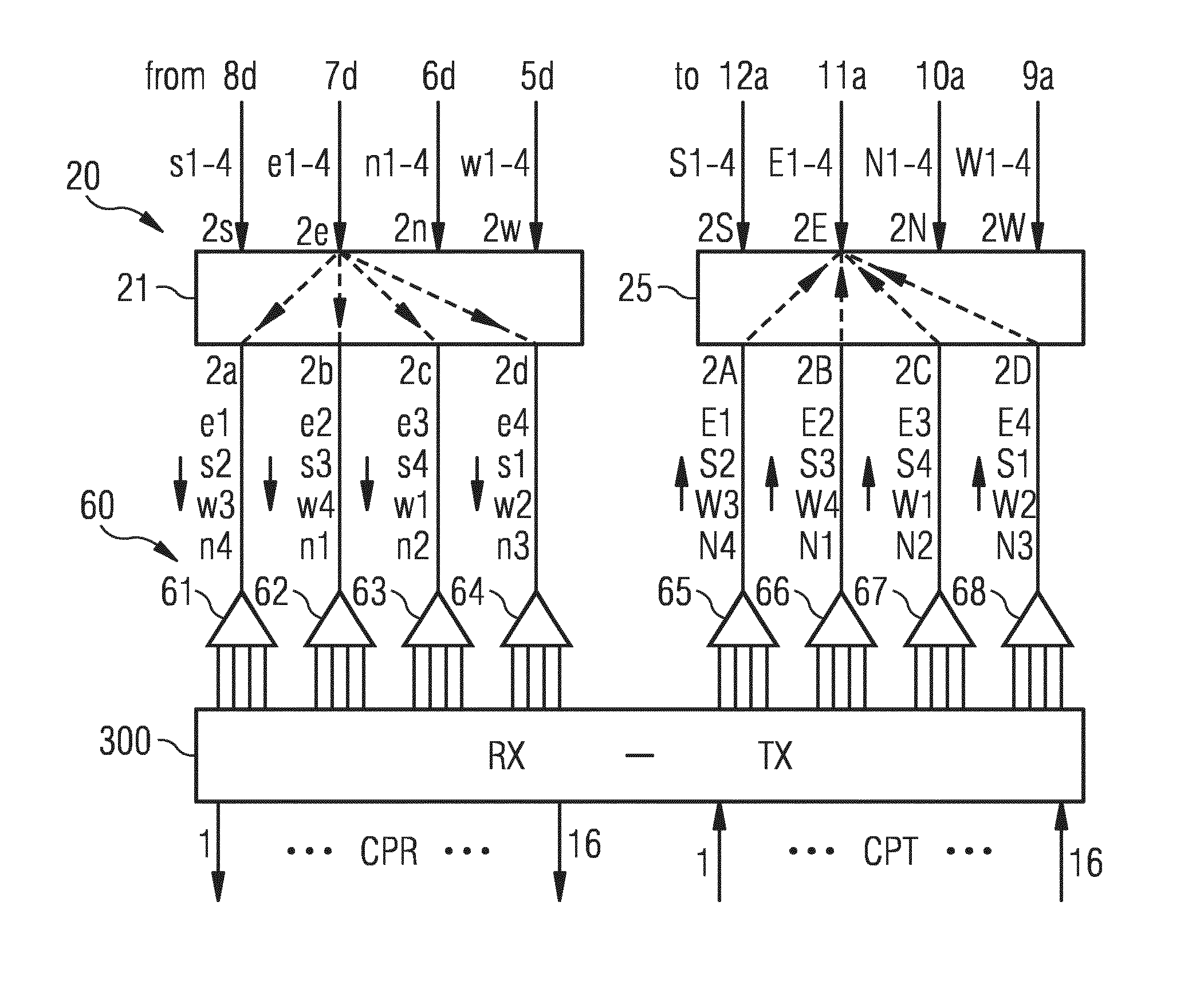
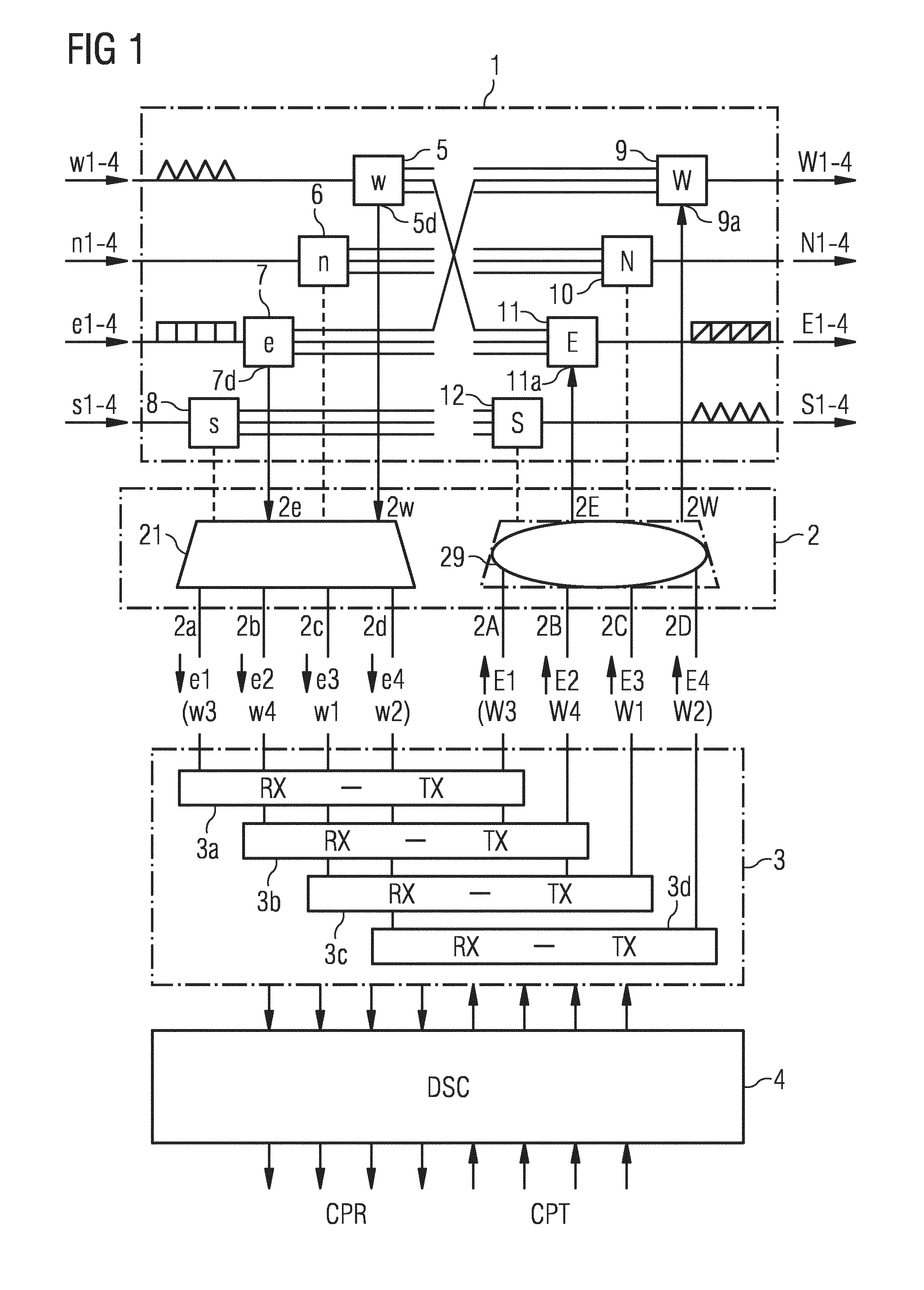
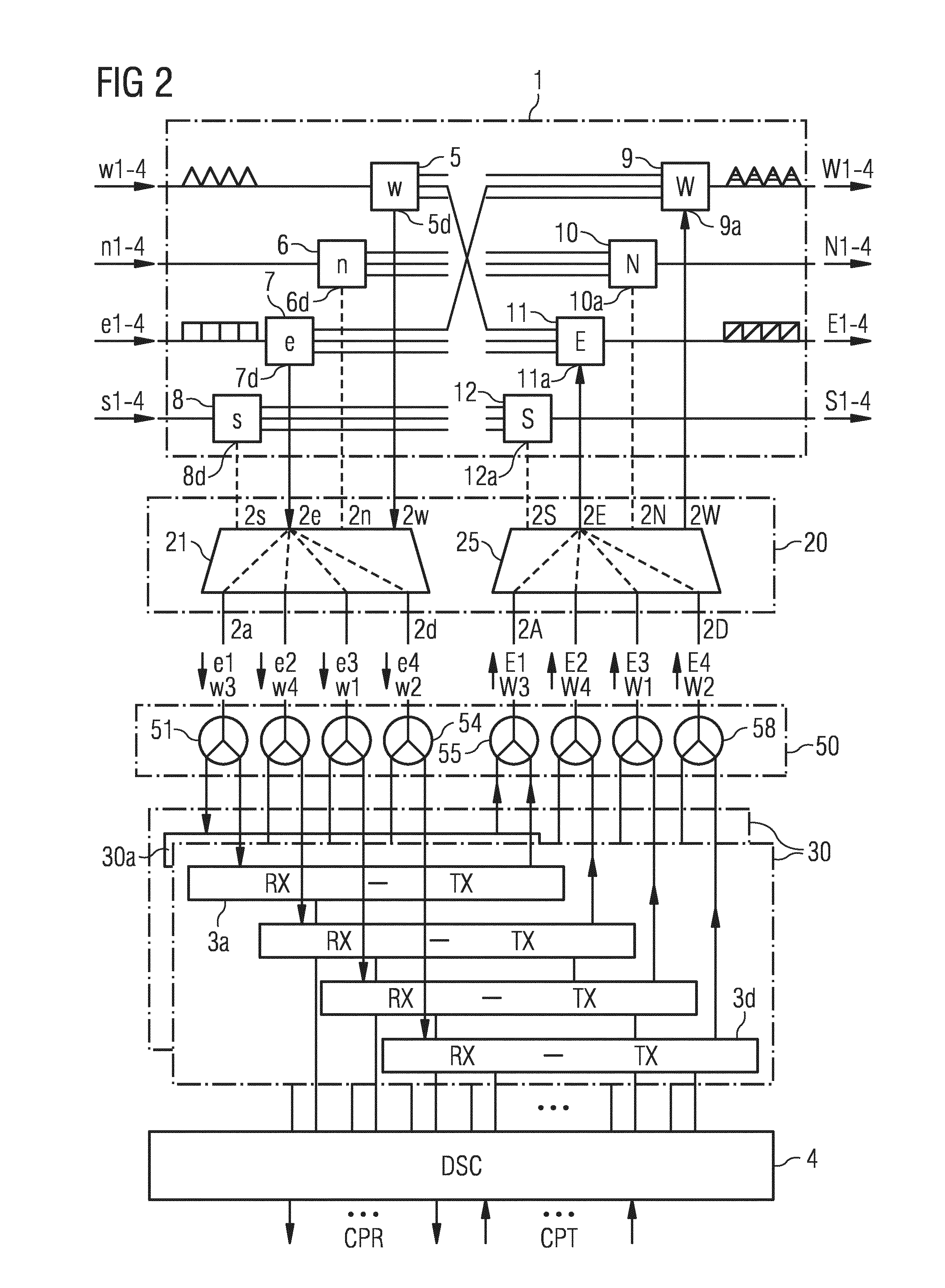
[0019]FIG. 1 illustrates a block diagram of a cross-connect. Only the functional elements relating to a basic embodiment of the invention are shown. E.g. optical amplifiers, attenuation elements, additional switches or additional filters may be inserted in the signal (channel) paths.

[0020]A cross-connector comprises a cross-connect section 1 for receiving, cross-connecting and emitting channels. The expression “channel” is used here meaning a signal which is transmitted with an adequate wavelength in this channel. Usually, a receiving part comprises drop outputs for dropping single channels (signals), and a transmitting part comprises add inputs for adding channels.

[0021]The depicted cross-connect comprises in the receiving part wavelength selective switches WSSs as distributing components 5-8 receiving super-channels from four directions w, n, e, s (west, north, east, south), and comprises in the transmitting part further WSSs as combiner components 9-12 emitting super-channels in ...


PUM


Abstract

A photonic cross-connect arrangement is presented which is able to cope with the transmission of super-channels, wherein complete super-channels are dropped and added to change a direction of transport. At least a cyclic filter is used in a drop-branch of a cross-connect for dividing a super-channel into sub-channels and/or at least a further cyclic filter is used in an add-branch to configure a super-channel.

Description

FIELD OF THE INVENTION[0001]The invention refers to a PHOTONIC CROSSCONNECT WITH RECONFIGURABLE ADD-DROP-FUNCTIONALITY.BACKGROUND OF THE INVENTION[0002]The invention is directed to a photonic cross-connect with reconfigurable add-drop functionality. Photonic, also called optical, cross-connects are based on the idea that a channel from a plurality of received WDM signals (wavelength division multiplex signals) can be redirected into any one of transmitted WDM signals. Most of the cross-connects avoid wavelength conversion, because it is cost effective at the expense of reduced signal quality, if optical-electrical conversion and 3R-regeneration are not used. Another restriction for the signal quality comes from the wavelength selective elements. These problems increase, if DWDM signals (dense wavelength division multiplex signals) are transmitted.[0003]In future, high data-rates signals will be transported and routed through a network in frequency slots filled with a set of sub-chan...

Claims


Application Information

Patent Timeline
Patent Type & Authority Applications(United States)
IPC IPC(8): H04J14/02H04Q11/00
CPCH04J14/0212H04Q11/0005H04Q2011/0015H04Q2011/0016H04Q2011/0009H04J14/0213H04J14/021
Inventor SCHIMPE, ROBERT
Owner XIEON NETWORKS SARL
Why Eureka
Try Eureka