Time delay integration image sensor with detection of travelling errors

Inactive Publication Date: 2015-12-17
TELEDYNE E2V SEMICON SAS
View PDF5 Cites 21 Cited by
  • Summary
  • Abstract
  • Description
  • Claims
  • Application Information

AI Technical Summary

Benefits of technology

[0021]If the number of groups of pairs of columns is increased and if they are given relative positions that are all different, b

Problems solved by technology

A problem that may be encountered in these sensors is the risk of imprecise summation of the signals of the pixels in cases where the sensor shifts laterally with respect to the direction of the columns of pixels, or in cases where the travel speed varies with respect to the rate of integration and summation of the charges generated by the pixels belonging to a given colum

Method used


Image

  • Time delay integration image sensor with detection of travelling errors
  • Time delay integration image sensor with detection of travelling errors
  • Time delay integration image sensor with detection of travelling errors

Examples


Embodiment Construction

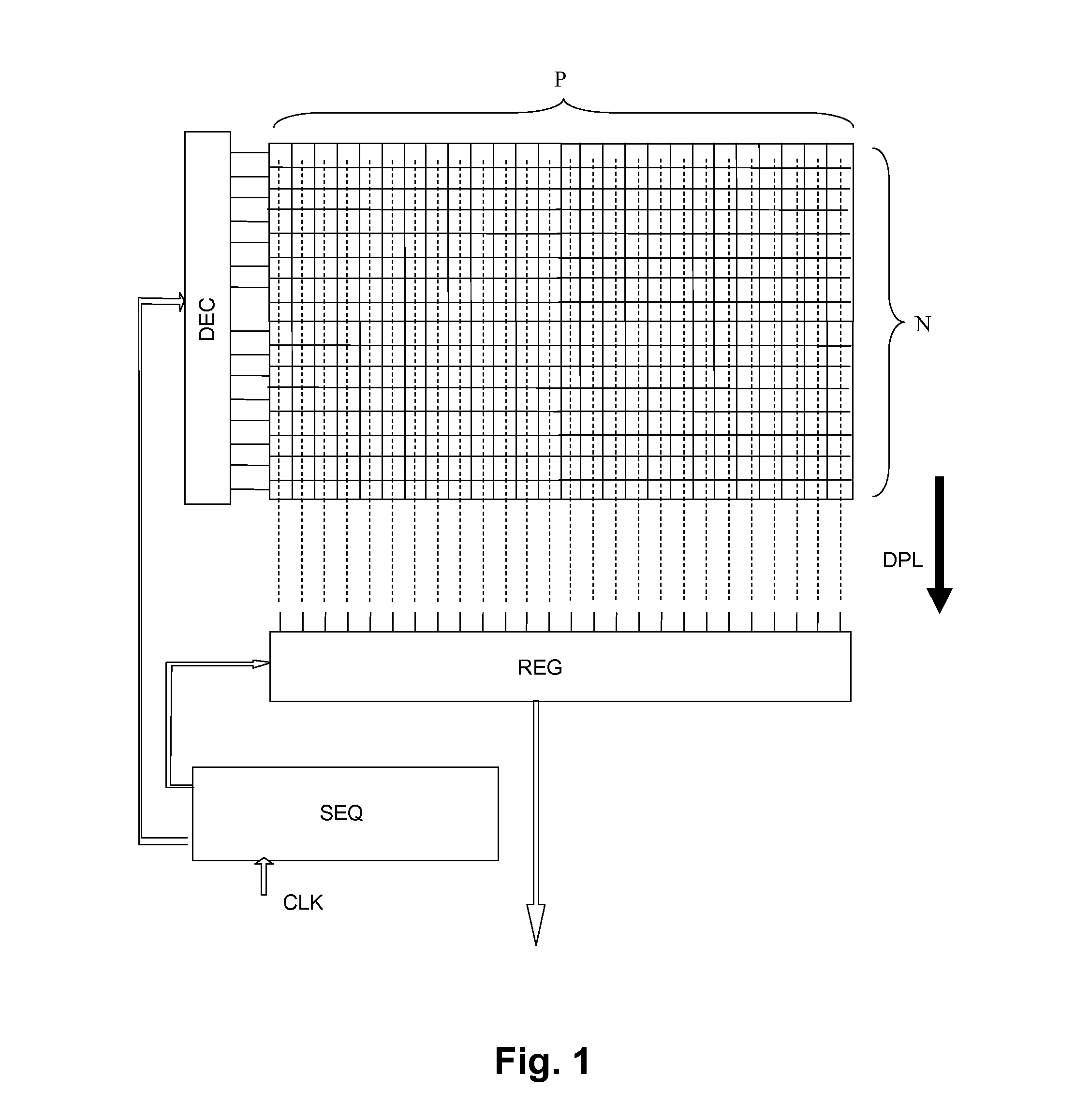
[0034]FIG. 1 schematically shows a TDI matrix image sensor, intended to operate with relative travel of the image with respect to the sensor in the direction of the columns of pixels. The arrow DPL indicates this relative direction of movement.

[0035]The sensor comprises P columns and N rows of pixels. Each row observes P points of an image line during an integration time Ti. The integration of charges is renewed with a period T. If a row of pixels of the sensor observes an image line during a first period, the following row of pixels observes the same image line during the following period, and so on. There is a precise synchronization between the integration period of the sensor and the relative travel speed between the sensor and the observed scene so that the relative movement of the image during the duration T corresponds exactly to a row pitch. If the row pitch is PL and the travel speed is V, charges are integrated and read cyclically with a period T=PL / V. If there are N rows ...


PUM


Abstract

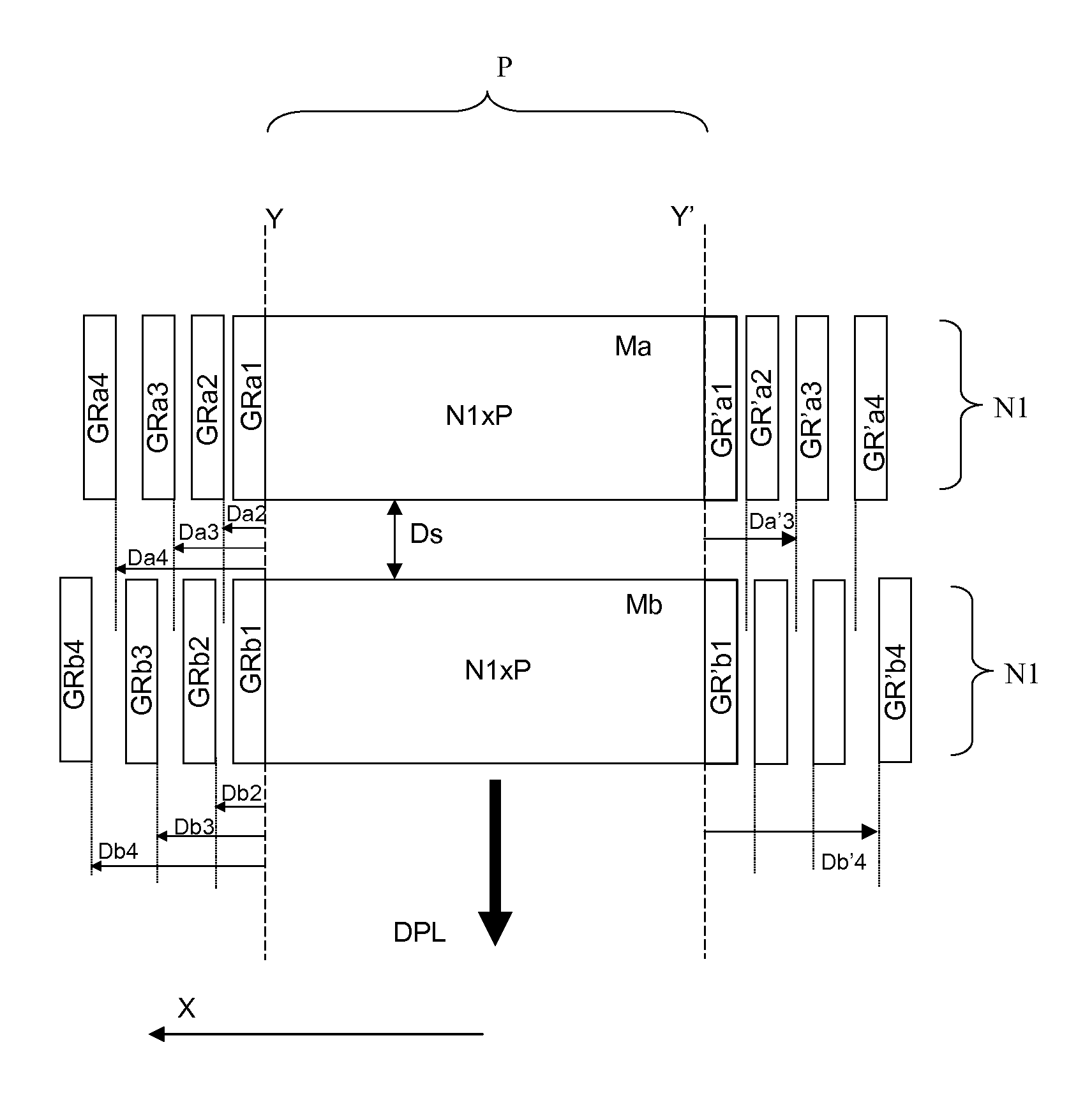
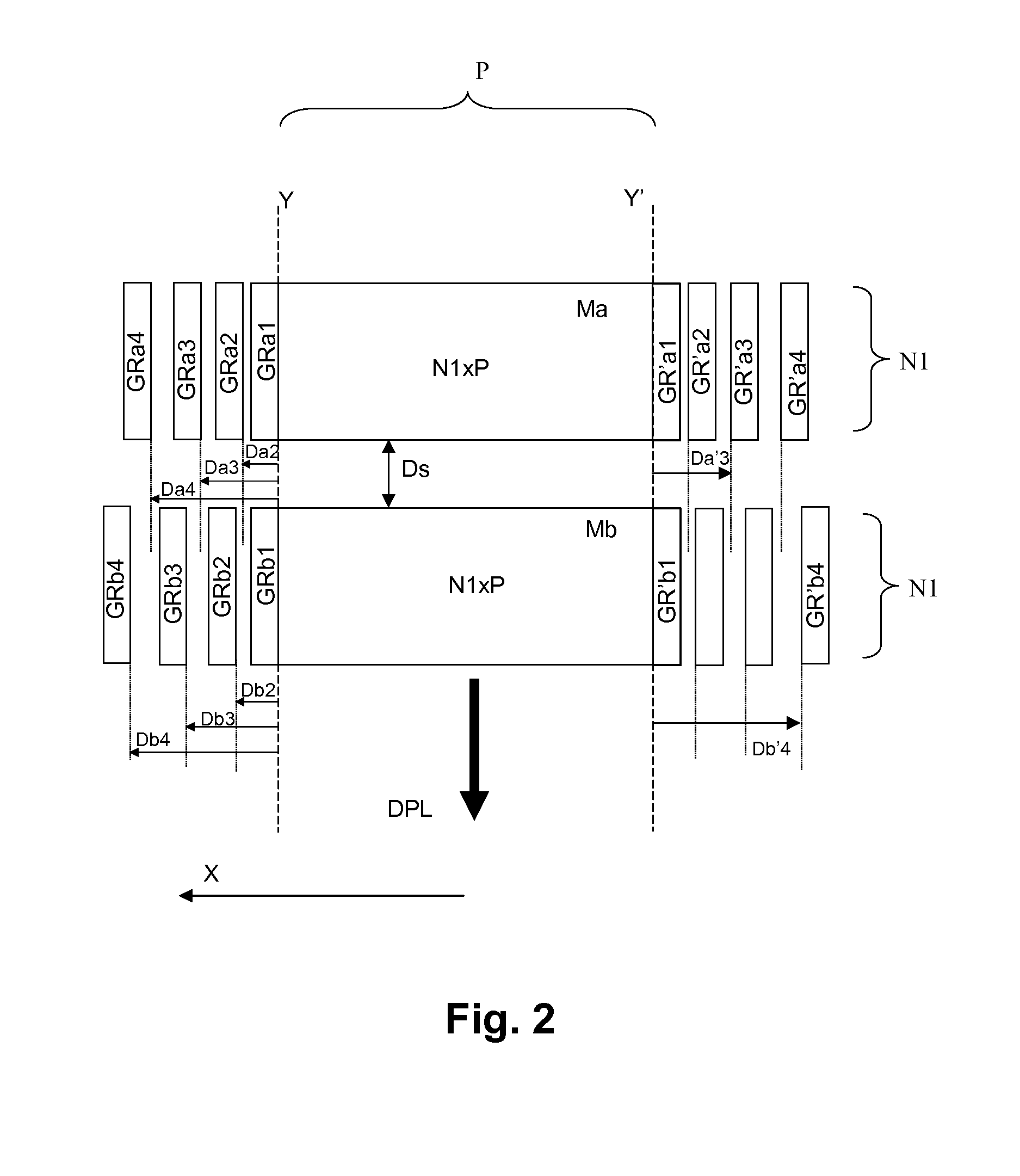
The invention relates to time delay integration (TDI) image sensors. The sensor includes means for detecting a shift of the sensor with respect to the image. The pixel matrix is divided in the column direction into at least a first and a second sub-matrix (Ma, Mb). On each side of each sub-matrix are arranged groups of additional columns (GRa1, GRb1, GRa2, GRb2). The shifts (Db2−Da2, Db3−Da3, etc.) in relative position of these groups between the first and the second sub-matrices are different from each other and make it possible to detect a relative shift of the sensor during travel. More precisely, the signals originating from groups of columns of same rank associated with the two sub-matrices are compared. The pair of groups that delivers the pair of signals that are closest to each other defines the probable shift of the sensor with respect to the image: this shift is equal to the relative position difference of these two groups.

Description

FIELD[0001]The invention relates to time delay integration image sensors, also called TDI sensors, in which an image of a line of points of an observed scene is reconstituted by adding together successive images taken by several photosensitive rows successively observing one and the same line of the scene as the scene travels in front of the sensor perpendicularly to the rows.DESCRIPTION OF PRIOR ART[0002]These sensors are for example used in satellite-based Earth observation sensors, or in systems for inspecting objects on conveyor belts. They comprise several parallel rows of photosensitive pixels; the sequencing of the control circuits of the various rows (control of exposure time then reading of the photogenerated charges) is synchronized with respect to the relative travel of the scene and of the sensor, so that all the rows of the sensor see the same line of the observed scene one after the other. The generated signals are then added together point-by-point for each point of t...

Claims


Application Information

Patent Timeline
IPC IPC(8): H04N5/372H04N5/232H04N5/374
CPCH04N5/37206H04N5/23264H04N5/3743H04N5/372H04N25/711H04N25/768H04N23/682H04N25/71
Inventor MAYER, FREDERICDE MONTE, BERTRAND
Owner TELEDYNE E2V SEMICON SAS
Why Eureka
Try Eureka