Releasable optical element

Active Publication Date: 2015-12-24
KONINKLIJKE PHILIPS ELECTRONICS NV
View PDF0 Cites 17 Cited by
  • Summary
  • Abstract
  • Description
  • Claims
  • Application Information

AI Technical Summary

Benefits of technology

[0011]An advantage of the present invention is that the optical element may easily be mounted to a lighting module without the use of tools and without the need for manual access to the lighting module during mounting. Furthermore, in some embodiments, the optical element may be mounted to lighting modules having a different configuration as no particular receiving portion is required on the lighting module. Additionally, the optical element may be suitable to be mounted on lighting modules having somewhat different diameters as the amount of deformation of the deformable member determines the inner diameter of the optical element. Furthermore, the deformable member may be replaceable to allow for further customization of the optical element, offering even greater flexibility in the range of lighting modules on which the optical member may be mounted by providing deformable members having varying inner diameters.
[0012]In one embodiment of the invention, the inner member may preferably be movable in an axial direction in relation to the outer member through a rotation of the inner member in relation to the outer member.
[0013]According to one embodiment of the invention, the cylindrical portion of the inner member facing the lighting module may comprise at least one structure configured to interact with at least one corresponding structure of the lighting module such that the inner member is inhibited from rotating when the outer member is rotated during mounting of the optical element on the lighting module. The interacting structures of the inner member and the lighting module may for example be a protrusion of the inner member interacting with a corresponding recess of the lighting module such that the inner member does not rotate in relation to the lighting module while the optical element is being mounted on the lighting module. As is apparent to the person skilled in the art, the opp

Problems solved by technology

In applications where the luminaire is countersunk into the surrounding material or where the space surrounding the luminaire is otherwise restricted, it may be difficult or even impossible to manu

Method used


Image

  • Releasable optical element
  • Releasable optical element
  • Releasable optical element

Examples


Embodiment Construction

[0027]In the present detailed description, various embodiments of an optical element will be described mainly with reference to an optical element for releasably mounting on a lighting module.

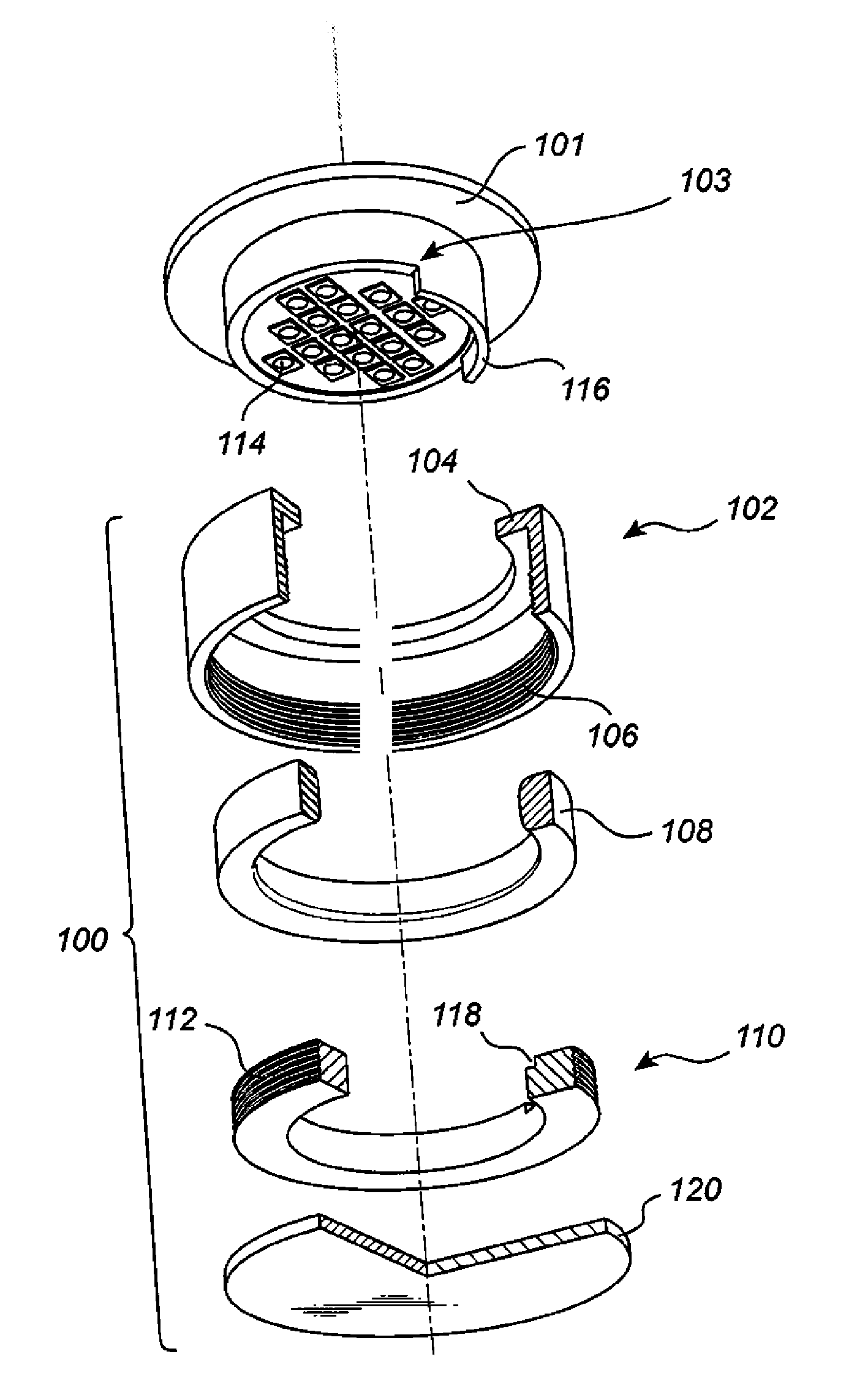
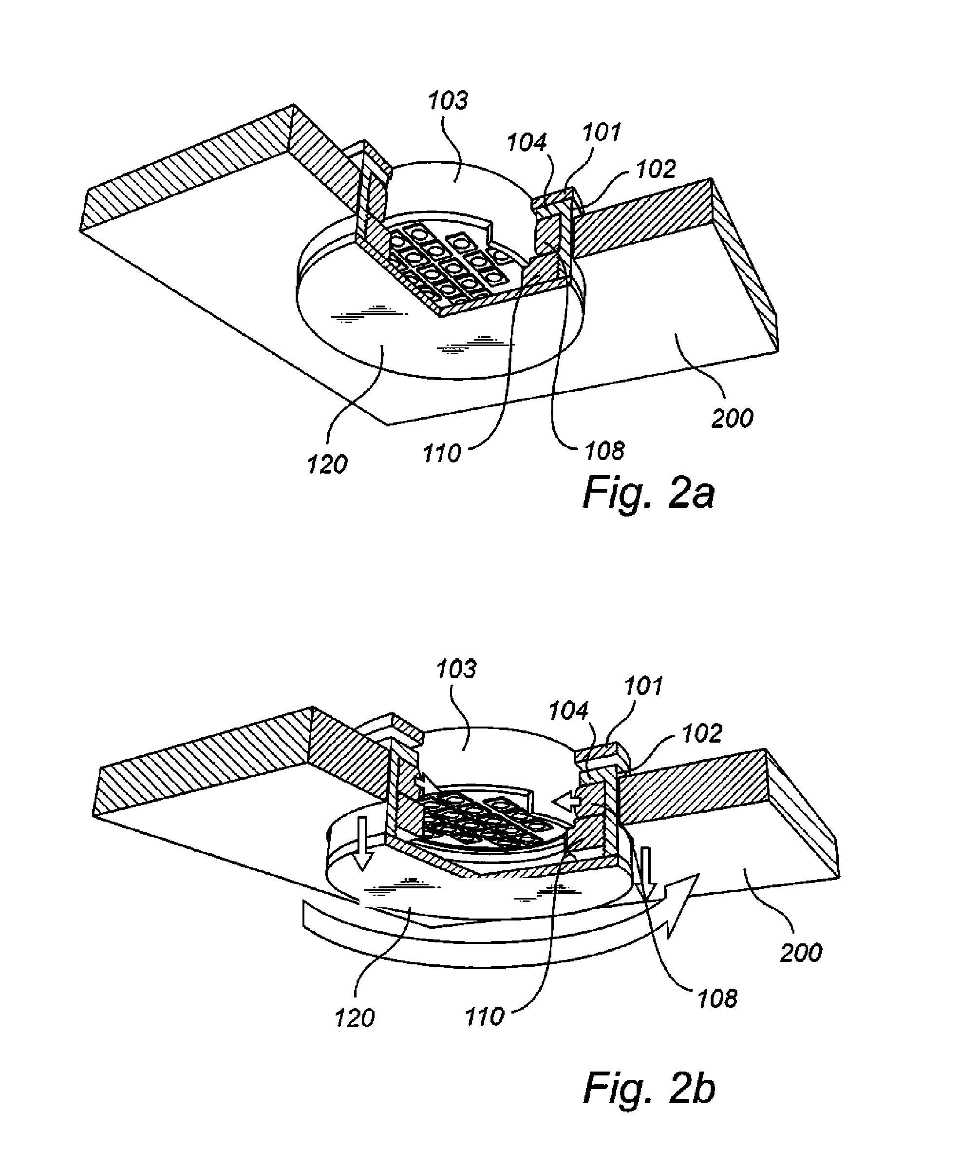
[0028]In the exploded view in FIG. 1, an optical element 100 according to an embodiment of the invention is schematically illustrated. The optical element 100 comprises an outer member 102, an inner member 110, a deformable ring 108 and an optical member 120.

[0029]The outer member 102 in turn comprises a cylindrical portion which is provided with screw threads 106 on the inner surface of the cylindrical portion and a shoulder portion 104 extending towards a central axis of the cylindrical portion. The inner member is provided with corresponding screw threads 112 on its outer surface for engaging the screw threads 106 of the outer member 102. Moreover, the deformable ring is arranged between the base of the cylindrical portion of the inner member 110 and the shoulder portion 104 of the outer mem...


PUM


Abstract

An optical element (100) for releasable connection to a lighting module (103), the optical element comprising; an outer member (102) having a cylindrical portion, the cylindrical portion having a shoulder portion (104) extending towards a central axis of the cylindrical portion; an inner member (110) having a cylindrical portion at least partially arranged within the cylindrical portion of the outer member (102); wherein the optical element further comprises at least one deformable member (108) arranged within the cylindrical portion of the outer element adjacent to the shoulder; and at least one of the inner and the outer member comprising an optical member (120) for modifying light emitted from the lighting module; and wherein the inner member is movable in an axial direction in relation to the outer member to compress the deformable member between a base surface of the cylindrical portion of the inner member and the shoulder portion of the cylindrical portion of the outer member.

Description

FIELD OF THE INVENTION[0001]The current invention relates to an optical element, and to a lighting arrangement comprising such an optical element.BACKGROUND OF THE INVENTION[0002]In many lighting applications it may be desirable to be able to modify and replace different parts of the luminaire in order to achieve various lighting effects. Different effects may for example be achieved by changing optical elements such as reflectors or diffusing lenses.[0003]Such optical elements are typically screwed or clamped to the lamp holder. Mounting and removal of the optical elements may be done manually by placing the fingers around the optical element or it may require the use of a tool.[0004]Furthermore, it may be desirable to arrange luminaires in a recess in the ceiling or wall in which they are mounted in order to provide a low visible profile of the luminaire itself. In applications where the luminaire is countersunk into the surrounding material or where the space surrounding the lumi...

Claims


Application Information

Patent Timeline
IPC IPC(8): F21V17/12F21V5/04G02B5/02F21V7/00F21V9/16
CPCF21V17/12F21V7/00F21V5/04G02B5/02F21V9/16F21V17/002F21V17/162F21Y2115/10F21V9/30
Inventor CREUSEN, PETRUS MARTINUSKAANDORP, WOUTER PETRUS
Owner KONINKLIJKE PHILIPS ELECTRONICS NV
Why Eureka
Try Eureka