Surfacing notable changes occurring at locations over time

a technology of notable changes and locations, applied in image analysis, image enhancement, instruments, etc., can solve the problem that images returned to users may not demonstrate these changes in relevant contex

Active Publication Date: 2015-12-24
GOOGLE LLC
View PDF0 Cites 14 Cited by
  • Summary
  • Abstract
  • Description
  • Claims
  • Application Information

AI Technical Summary

Benefits of technology

[0003]Aspects of the disclosure provide a computer implemented method. The method includes identifying, by one or more computing devices, sets of images captured at a location over a period of time. The sets of images depict objects at the location. Using the computing devices, a first and a second 3D geometry of the location may be generated based on the sets of images. The first and second 3D geometries depict physical features of objects at the location at different times. Visual changes at the location over the period of time for a given physical feature of the objects depicted in images from the sets of images are determined, based on at least a comparison of features in corresponding areas of the first and second 3D geometries of the location. Thereupon, the sets of images are ranked based on the determined visual changes for each set of the sets of images and a given set of images from the sets of images may be selected based on the ranking. The given set of images depicting visual changes occurring over time at the location.
[0004]In one example, a request for imagery related to the location may be received. In response to the request, one or more images may be provided from the selected set of images. In this example, providing the one or more images may include determining whether the visual changes of the given physical feature in images from the selected set of images satisfies a predetermined change threshold level. When the visual changes satisfy the predetermined change threshold level, the one or more images are provided. In that regard, determining the visual changes may include determining change scores for the given physical feature depicted in corresponding areas of the first and second 3D geometries associated with the sets of images and selecting images from the sets of images based at least in part on the change scores. In some aspects, the first 3D geometry depicts objects at the location at a first time and the second 3D geometry depicts objects at the location at a second time. This second time may occur after the first time.
[0005]In another example, providing the one or more images may include identifying a landmark within a viewing angle of the selected images associated with the location and selecting images that depict changes to the landmark over time, or receiving a request for images of the location based on an identified physical fe

Problems solved by technology

However, as the landscape of these locations change, the images returned to the user may not demon

Method used


Image

  • Surfacing notable changes occurring at locations over time
  • Surfacing notable changes occurring at locations over time
  • Surfacing notable changes occurring at locations over time

Examples


Embodiment Construction

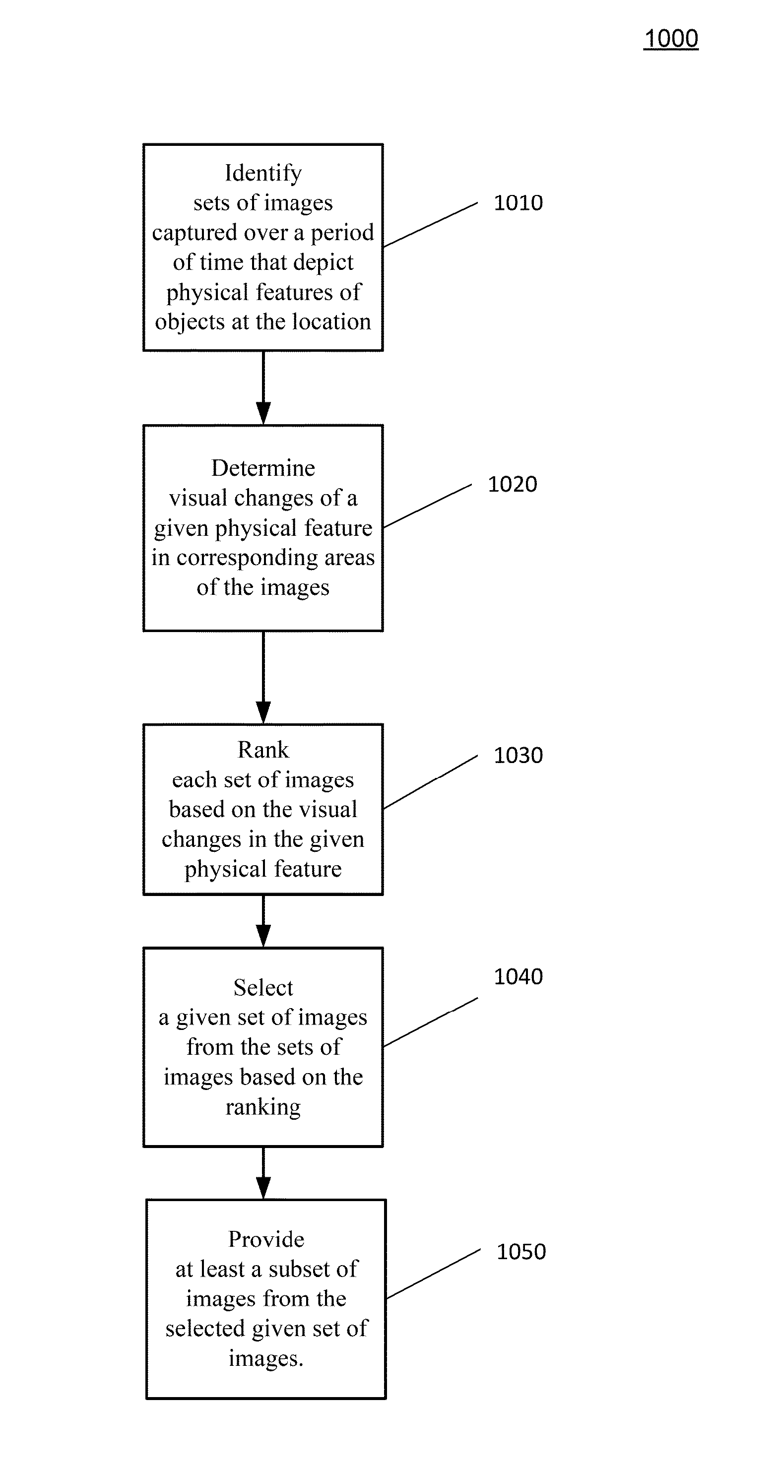
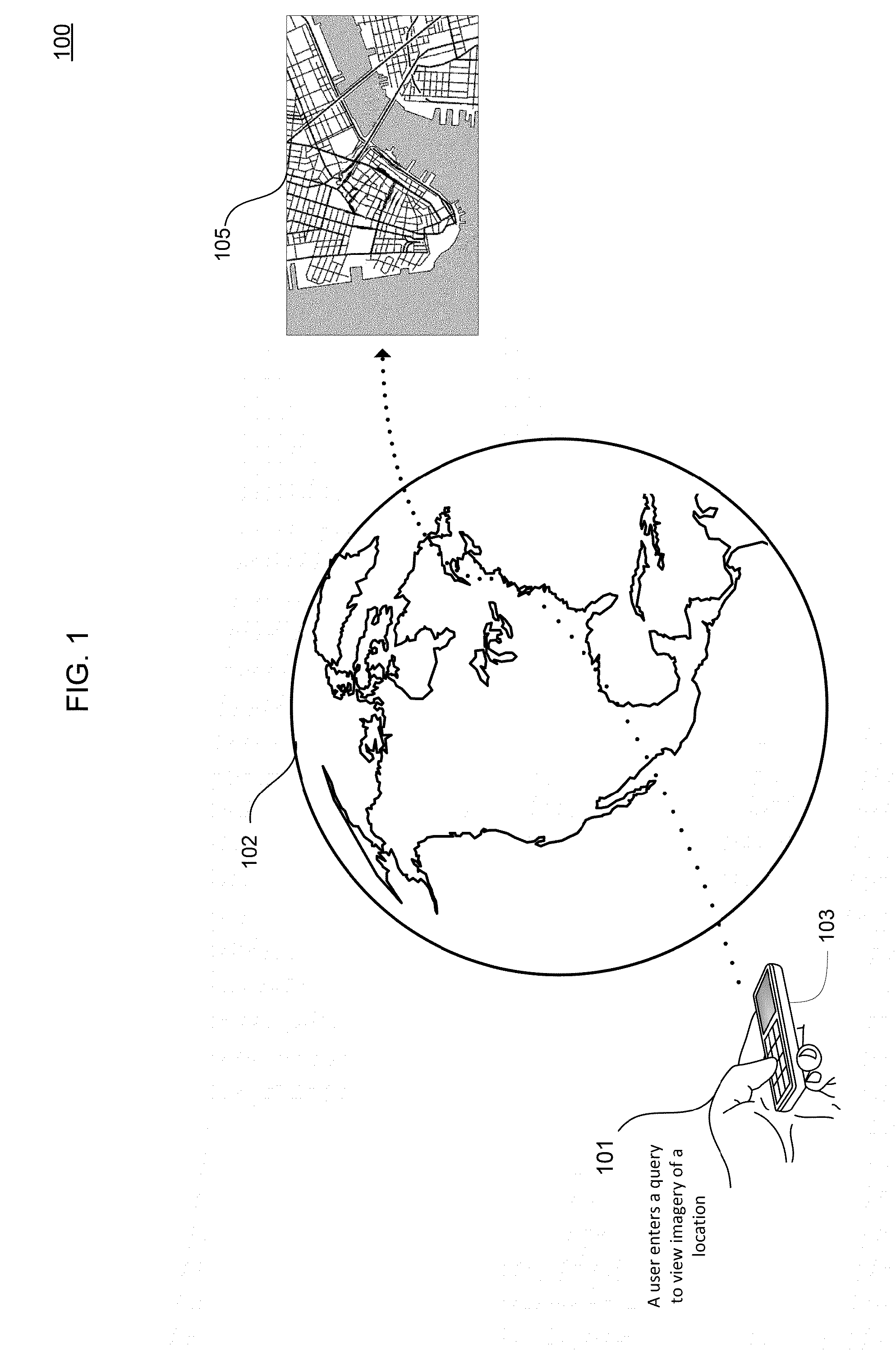
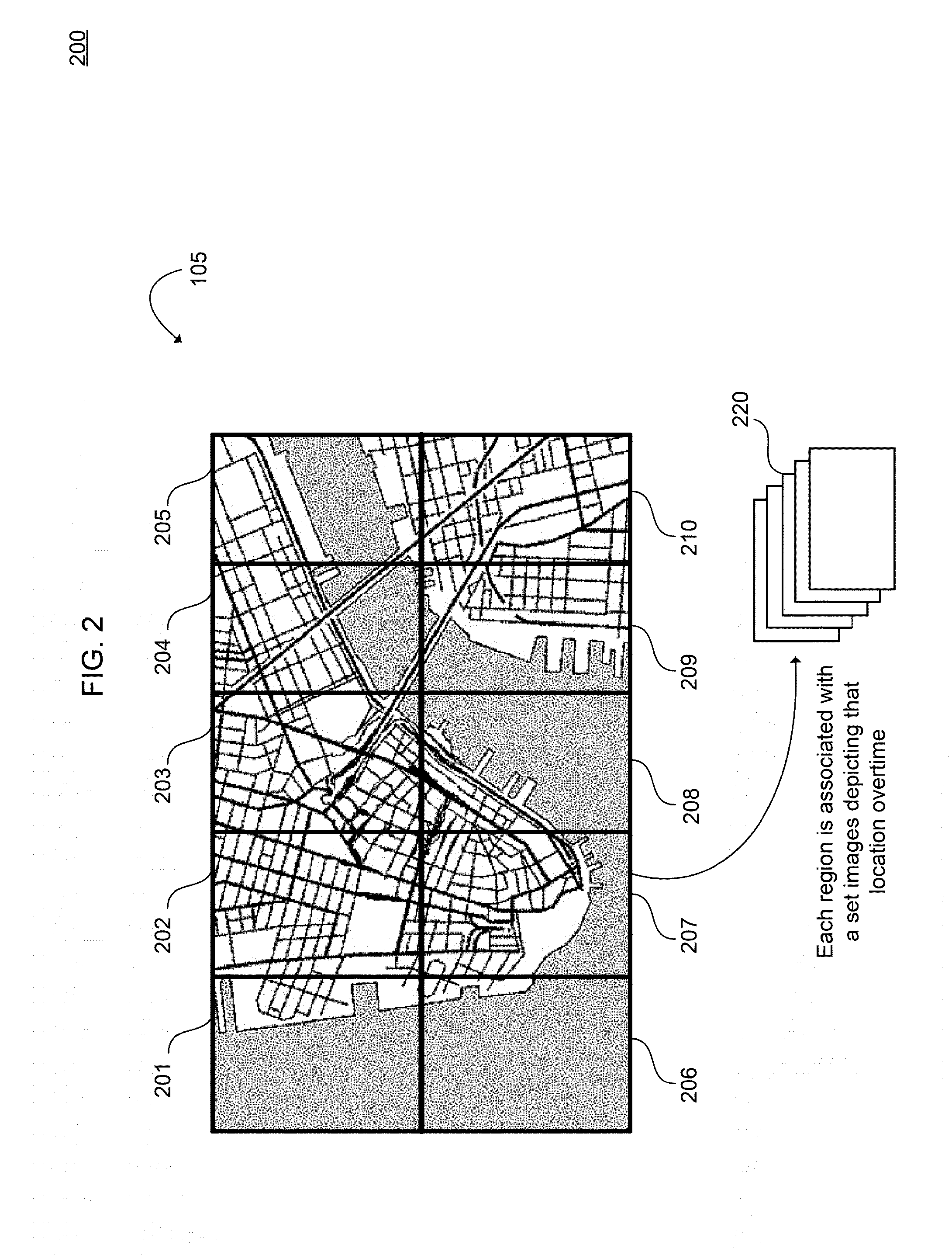
[0018]The present disclosure generally relates to techniques for providing a set of geographic imagery of a location that identifies or demonstrates notable feature changes that have occurred at the location over time. For example, a system may be provided that can surface or otherwise detect these notable feature changes by ranking sets of geographic imagery captured at the location over a given time period. The notable feature changes can include one or more regions of the location that has more visible or otherwise physical changes than in other regions of the location. For example, the notable feature changes can include construction changes to the location such as buildings being built on a vacant lot or buildings being modified to include new levels. In some embodiments, the notable feature changes can include areas of the location that have changed due to some type of destructive event like a fire, or where dilapidated buildings have been leveled or other variations to the lo...


PUM


Abstract

An exemplary method for surfacing feature changes occurring over time at a location is provided. The method includes identifying sets of images captured at a location over a period of time. The sets of images depict objects at the location. Visual changes at the location over the period of time are determined for a given physical feature of the objects depicted in images from the sets of images based on at least a comparison of features in corresponding areas of a first and a second 3D geometry of the location associated with the images. The first and second 3D geometries depict physical features of objects at the location at different times. The sets of images may be ranked based on the determined visual changes for each set. A given set of images from the sets of images may be selected for display on a user interface based on the ranking.

Description

BACKGROUND[0001]Various services may provide images of geographic locations to users. Typically in such services, a client computer may request imagery of a particular location and receive a plurality of images, such as digitized panoramic 360 photographs, in response. The images are received from different sources and may be grouped by locations where the images were taken. In some examples, these images may include photographs of real world locations, which may allow users to view these locations.[0002]User searches for maps and photos using such services for displaying imagery may often return images of a place at the most popular times for taking pictures and under perfect conditions. However, as the landscape of these locations change, the images returned to the user may not demonstrate these changes in relevant context to where the user can discover and consider such changes.BRIEF SUMMARY[0003]Aspects of the disclosure provide a computer implemented method. The method includes...

Claims


Application Information

Patent Timeline
IPC IPC(8): G06T7/00
CPCG06T7/0044G06T2200/04G06T2207/10028G06T2207/10032G06T2207/20021G06T2207/30184G06T7/254
Inventor SIEGEL, JONATHANHUTCHISON, ALLENLI, WENFENG
Owner GOOGLE LLC
Why Eureka
Try Eureka