
Electronic device with antenna having ring-type structure

a technology of electronic devices and antennas, applied in the direction of elongated active elements, resonant antennas, antenna earthings, etc., can solve the problems of reducing the radiation efficiency of antennas, unable to design the relationship between performance and size in a complementary manner, and unable to achieve the requisite performance over a desired band or band

Active Publication Date: 2015-12-24
SAMSUNG ELECTRONICS CO LTD
View PDF6 Cites 89 Cited by
  • Summary
  • Abstract
  • Description
  • Claims
  • Application Information

AI Technical Summary

Benefits of technology

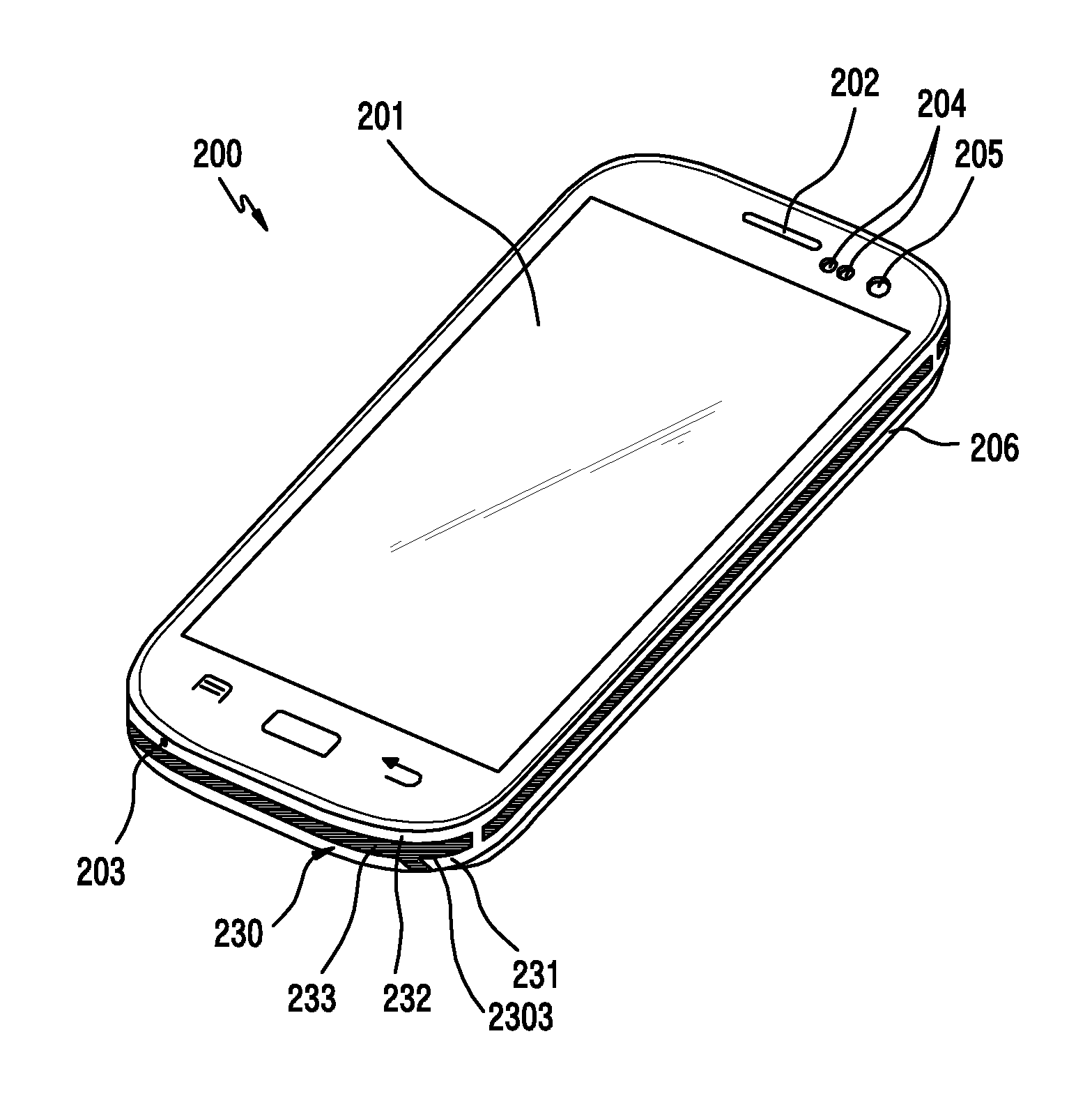
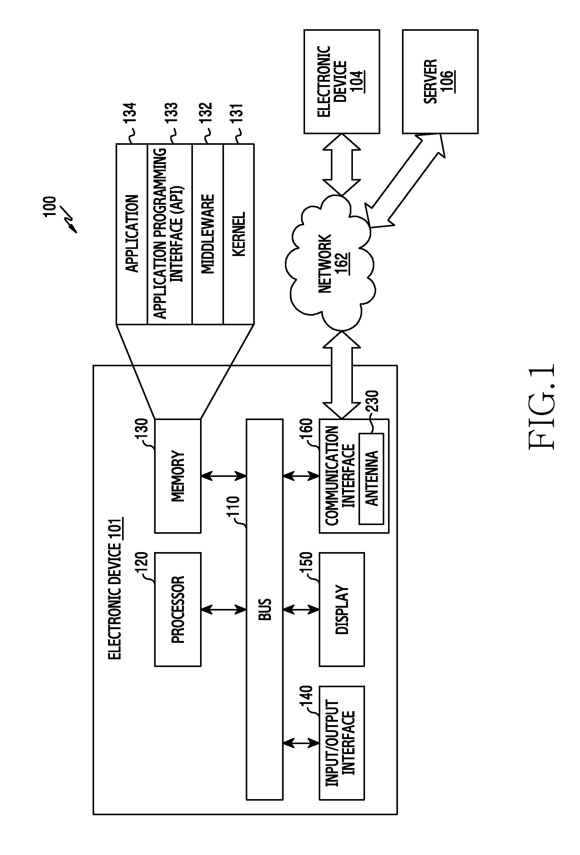
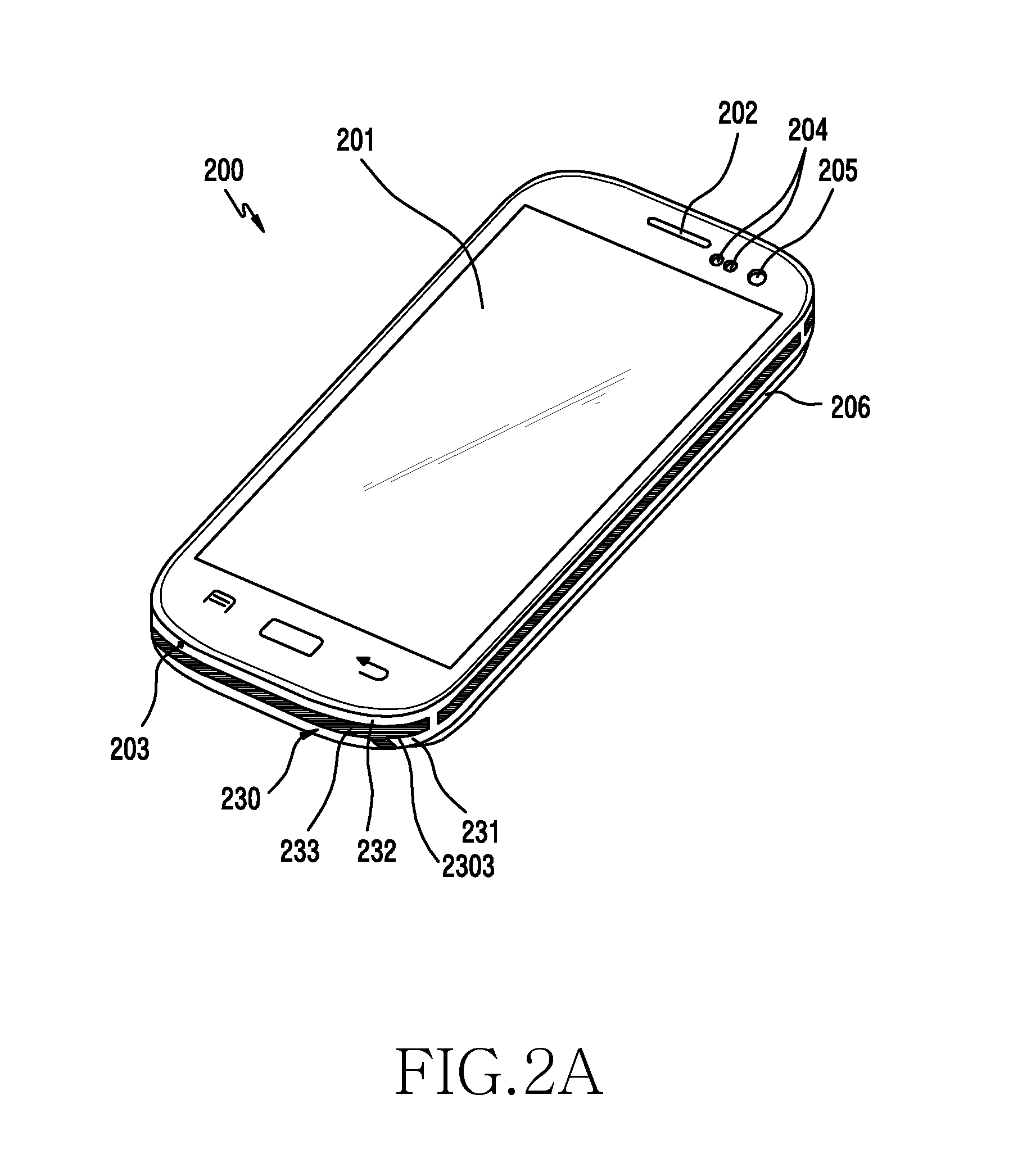
The present disclosure describes an electronic device with a ring-type antenna structure that serves as a part of its external appearance or housing. The antenna includes a metal bracket and a first metal ring that surrounds it. The first metal ring has at least two sections separated by a gap, with one section operating as a radiator for RF feeding. The electronic device also has a display and a substrate with an antenna feeder for feeding the first metal ring. The first metal ring acts as a monopole, PIFA, or loop antenna, depending on the suitable feeding method. The technical effect is that the antenna structure provides improved signal performance without impacting the overall design of the electronic device.

Problems solved by technology

Disadvantageously, however, a performance-to-size relation cannot be designed in a complementary manner.
In particular, when a metal construction and a metal component are located near the antenna, there is a problem in that the antenna's radiation efficiency is decreased and a requisite performance over a desired band or bands is also diminished.
However, with the trend towards smaller and thinner devices, a space for placing the antenna has been more and more constrained, and a distance to a surrounding metal construction and metal component is becoming increasingly closer.
However, it is difficult for the aforementioned conventional general built-in antenna to satisfy a requirement of a compact size, efficiency increase, and a wide band in such extreme surrounding conditions.
However, in the first approach, there is a limit to how close the radiator can be to the metal construction and also effectively operate, which limits the ability to shrink the electronic device size and / or thickness.
In addition, a method of performing an insert molding process on an antenna part impairs an external appearance of the antenna since there is a disparity between metal and insert molding processes in a design aspect even if it is easy to ensure radiation efficiency.
However this arrangement typically results in a radiation deterioration phenomenon.
That is, if there is a metal structure extended from the ground near the antenna, near field radio frequency (RF) energy induces current in a corresponding metal member and generates thermal loss and radiation loss together with lossy volume, thereby resulting in overall radiation efficiency deterioration.
However, this method has a problem in that a disparity occurs between metal and insert molding processes in a design aspect.

Method used


Image

  • Electronic device with antenna having ring-type structure
  • Electronic device with antenna having ring-type structure
  • Electronic device with antenna having ring-type structure

Examples


Embodiment Construction

[0025]Hereinafter, various exemplary embodiments of the present disclosure are described with reference to the accompanying drawings. While the various exemplary embodiments of the present disclosure are susceptible to various modifications and alternative forms, a specific embodiment thereof has been shown by way of example in the drawings and will herein be described in detail. It should be understood, however, that it is not intended to limit the various exemplary embodiments of the present disclosure to the particular form disclosed, but, on the contrary, the various exemplary embodiments of the present disclosure are to cover all modifications, equivalent, and alternatives falling within the spirit and scope of the various exemplary embodiments of the present disclosure as defined by the appended claims. Like reference numerals denote like constitutional elements throughout the drawings.

[0026]The expression “include” or “may include” used in the various exemplary embodiments of...


PUM


Abstract

Various exemplary embodiments of the present disclosure may provide an electronic device including an antenna with a ring-type structure. The electronic device includes a metal bracket and the antenna. The antenna includes a first metal ring surrounding the metal bracket, where the first metal ring has at least two sections separated by at least one gap. At least one section may operate as a radiator through radio frequency (RF) feeding at least at one portion thereof. A second metal ring may be electrically connected, at least at one point thereof, to a ground of the electronic device or to the first metal ring. At least one section of the first metal ring may operate as a monopole antenna, as a PIFA antenna, or as a loop antenna, via suitable feeding.

Description

CLAIM OF PRIORITY[0001]This application claims the benefit under 35 U.S.C. §119(a) of a Korean patent application filed in the Korean Intellectual Property Office on Jun. 23, 2014 and assigned Serial No. 10-2014-0076496, the entire disclosure of which is hereby incorporated by reference.BACKGROUND[0002]1. Technical Field[0003]The present disclosure relates generally to an electronic device and an antenna for an electronic device, and more particularly to an antenna suitable for a portable electronic device such as a hand held electronic device.[0004]2. Description of the Related Art[0005]With recent technical advances, commercialized portable electronic devices (also referred to generally as mobile communication devices) may include a wireless communication function operating in several frequency bands. Consumers who use a portable electronic device demand a smaller device having various functions. To satisfy consumer demand, manufacturers continually strive to reduce the size of co...

Claims


Application Information

Patent Timeline
Patent Type & Authority Applications(United States)
IPC IPC(8): H01Q1/24
CPCH01Q1/243H01Q9/0421H01Q9/0485H01Q1/36H01Q1/48H01Q9/42
Inventor LEE, WOO-SUPKIM, GYU-SUBKIM, YEON-WOOPARK, JUNG-SIK
Owner SAMSUNG ELECTRONICS CO LTD
Learn More