Device for maintaining alignment of a cannulated shaft over a guide pin

Active Publication Date: 2015-12-31
HOWMEDICA OSTEONICS CORP
View PDF15 Cites 16 Cited by
  • Summary
  • Abstract
  • Description
  • Claims
  • Application Information

AI Technical Summary

Benefits of technology

[0008]There is a need for new apparatuses and methods for maintaining alignment between a guide pin and a hollow shaft of a drill bit or other tool for driving an implement or implant. Such apparatuses and methods preferably provide one or more immediately visible, audible, and/or vibratory indications of such structures being non-parallel or otherwise off-set or out of alignment. When using a drill or other driver equipped with a dri

Problems solved by technology

Such simple techniques are adequate for gross alignment of the direction of advance of a drill bit but are inadequate where higher precision is desired.
Also, the guide pin outside of the bone can be bent at an angle relative to the guide pin inserted in the bone thereby not guiding the dr

Method used


Image

  • Device for maintaining alignment of a cannulated shaft over a guide pin
  • Device for maintaining alignment of a cannulated shaft over a guide pin
  • Device for maintaining alignment of a cannulated shaft over a guide pin

Examples


Embodiment Construction

[0033]While the present description sets forth specific details of various embodiments, it will be appreciated that the description is illustrative only and should not be construed in any way as limiting. Furthermore, various applications of such embodiments and modifications thereto, which may occur to those who are skilled in the art, are also encompassed by the general concepts described herein. Each and every feature described herein, and each and every combination of two or more of such features, is included within the scope of the present invention provided that the features included in such a combination are not mutually inconsistent.

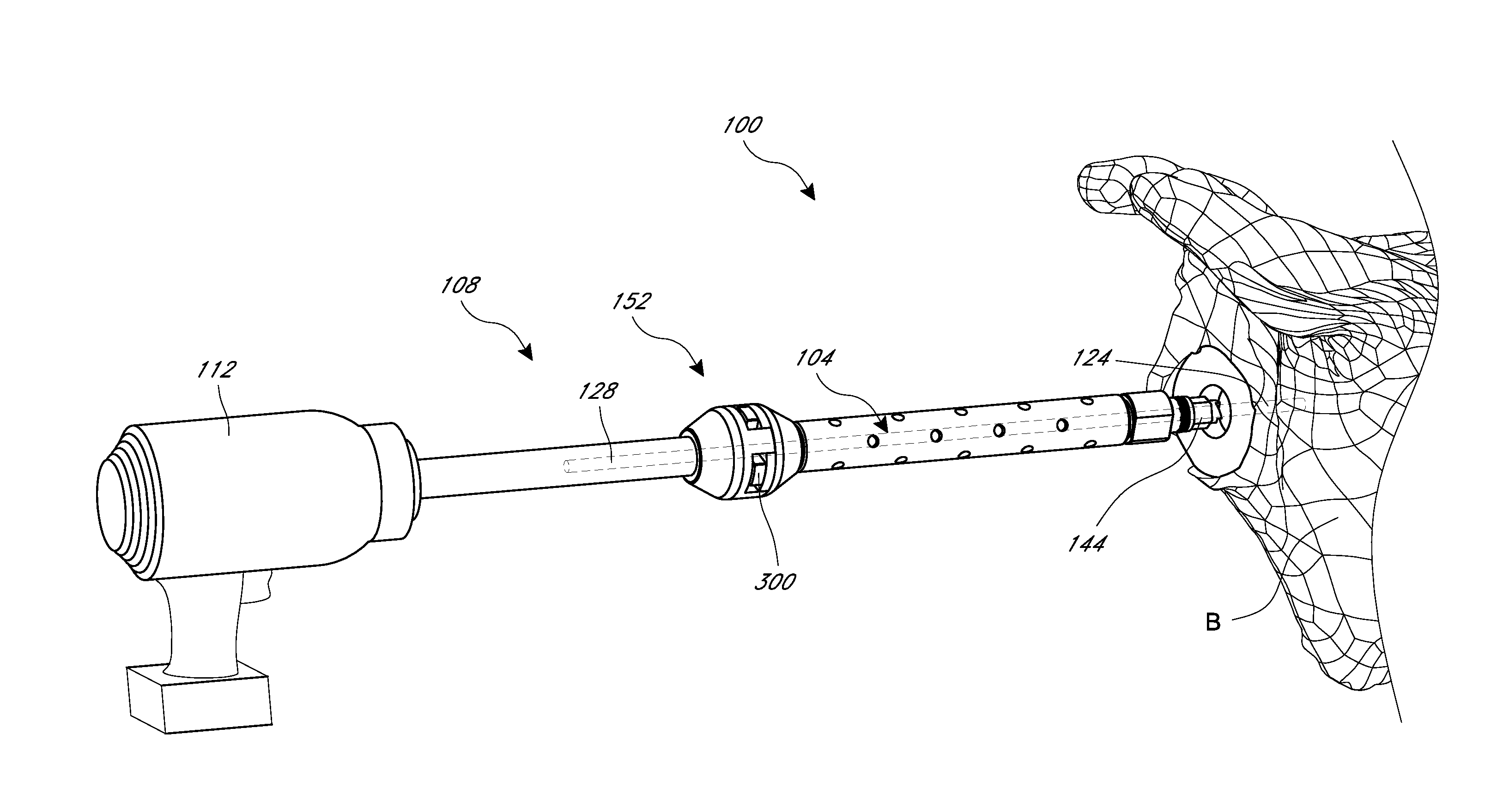
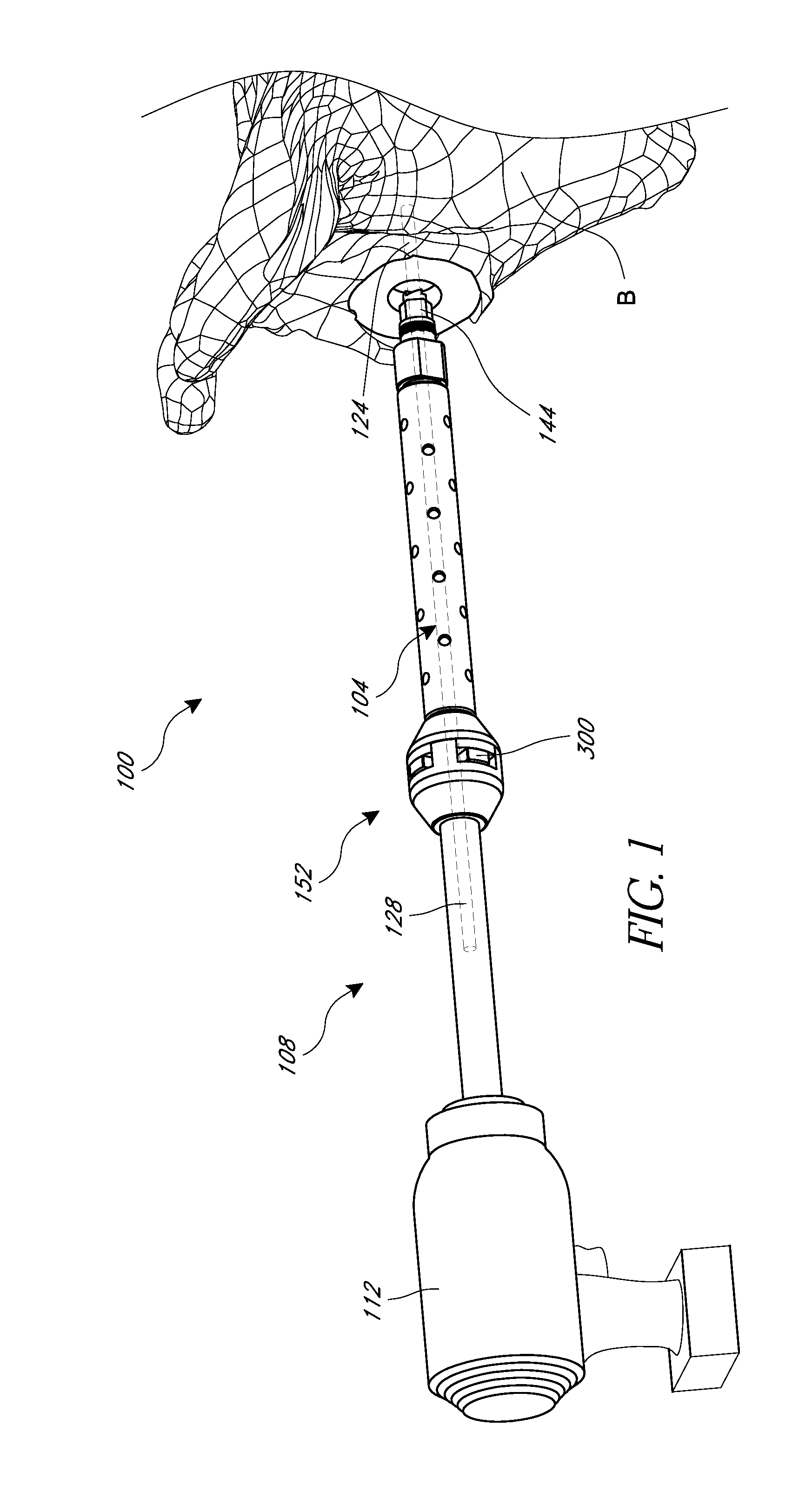
[0034]FIG. 1 shows an orthopedic driver system 100 that includes a guide pin 104, a tool assembly 108, and a drill 112. In the illustration, a distal portion of the system 100 is disposed in the bone B and a proximal portion is coupled with the drill 112. The bone B can be a portion of a shoulder, for example a portion of a scapula.

[0035]The guid...


PUM


Abstract

An orthopedic driver is provided that includes an elongate tubular body and an indicator assembly. The indicator assembly has a housing that has at least one opening and a visual indicator disposed in the at least one opening. The visual indicator is configured to be coupled with a guide pin such that lateral movement of the elongate tubular body relative to the guide pin causes the visual indicator to move between a flush or recessed configuration within the housing and an extended configuration. In the extended configuration, the visual indicator extends outward of an outer surface of the housing. The flush or recessed configuration corresponds to alignment of the guide pin relative to the elongate tubular body and the extended configuration corresponds to misalignment of the guide pin relative to the elongate tubular body.

Description

INCORPORATION BY REFERENCE TO ANY PRIORITY APPLICATIONS[0001]Any and all applications for which a foreign or domestic priority claim is identified in the Application Data Sheet as filed with the present application are hereby incorporated by reference under 37 C.F.R. §1.57.BACKGROUND OF THE INVENTION[0002]1. Field of the Invention[0003]This application relates to apparatuses and methods for maintaining alignment of cannulated shafts over slender guide structures, such as guide pins.[0004]2. Description of the Related Art[0005]It is conventional in orthopedics to use a drill or other driver tool equipped with a drill bit to modify bone and to deliver implants into a bone surface or cavity. A surgeon can use a simple technique to guide the advancement of the drill bit, such as simply visually confirming that the drill bit is advancing in a proper direction relative to the bone surface or cavity. Such simple techniques are adequate for gross alignment of the direction of advance of a d...

Claims


Application Information

Patent Timeline
IPC IPC(8): A61B17/17A61B17/16
CPCA61B17/17A61B17/1633A61B17/1684A61B2017/00119A61B17/1778A61B17/1624A61B17/1628A61B17/1631A61B2017/681
Inventor COURTNEY, JR., ROBERTHODOREK, BRIAN C.PURDY, MATTHEW J.
Owner HOWMEDICA OSTEONICS CORP
Why Eureka
Try Eureka