Methods and systems for treating produced water

a technology of purification system and produced water, which is applied in the direction of multi-stage water/sewage treatment, treatment water, and borehole/well accessories, etc. it can solve the problems of membrane separation performance degradation, membrane scaling quickly degrades membrane separation performance, and further commercial use of membrane purification systems, so as to achieve less complex pretreatment

Inactive Publication Date: 2015-12-31
CHEVROU USA INC
View PDF3 Cites 19 Cited by
  • Summary
  • Abstract
  • Description
  • Claims
  • Application Information

AI Technical Summary

Benefits of technology

[0007]The present invention is directed to producing purified water from produced water that is recovered from a well extending into a subterranean formation, in a method that includes use of membrane separation system. The method includes pretreating the produced water to produce clarified water for membrane purification. Conventional pretreatment typically involves a number of separate process steps for particulate and oil removal, hardness reduction and significant pH adjustment, in some cases to a pH of greater than 10, to conventionally prepare produced water for membrane purification. At least in part, the invention relates to mechanisms and methods for operating a simplified membrane purification system with a significantly less complex pretreatment relative to conventional methods for water purification.

Problems solved by technology

However, the conventional methods for using RO (reverse osmosis) membrane systems for water purification require careful and extensive pretreatment of the produced water prior to purification in the membrane purification system.
Produced water frequently contains oil, solid particulates and high amounts of hardness, all of which easily cause scaling issues in a membrane purification system.
Membrane scaling quickly degrades membrane separation performance; it is one of the continuing factors that prevent further commercial employment of membrane purification systems for water purification.
While adding sufficient alkali to the produced water to achieve this high pH value (at a significant cost and at additional operating complexity), difficulties arise with separating some of the contaminants from the produced water.
Operating the membrane purification system at a high pH may not even be effective for achieving a desired level of water purification.

Method used


Image

  • Methods and systems for treating produced water
  • Methods and systems for treating produced water
  • Methods and systems for treating produced water

Examples


example 1

[0114]A packed column about 8 feet high and about 9.5 inches in diameter (ID) was packed with approximately 80 pounds of ¼ inch and finer size crushed oyster shells. An aqueous solution containing organic contaminants, including BTEX compounds (benzene, toluene, ethyl-benzene and the xylenes) and soluble organics (soluble oil), was introduced at the top of the column at a flow rate between 0.4 and. 2.0 gpm. The average flow rate was maintained at approximately 1.0 gpm. Water was collected at the bottom of the column and analyzed using gas chromatography.

[0115]The results of the soluble organic and BTEX content in the inlet and outlet streams of the column are given in Table V. The detectable limit for the BTEX compounds was 0.1 ng / L. The total hydrocarbon was obtained using the purge and trap method. All dispersed oil was removed from the feed solution before entering the packed column, and the total hydrocarbon was therefore essentially soluble organics (or soluble oil).

TABLE VConc...

example 2

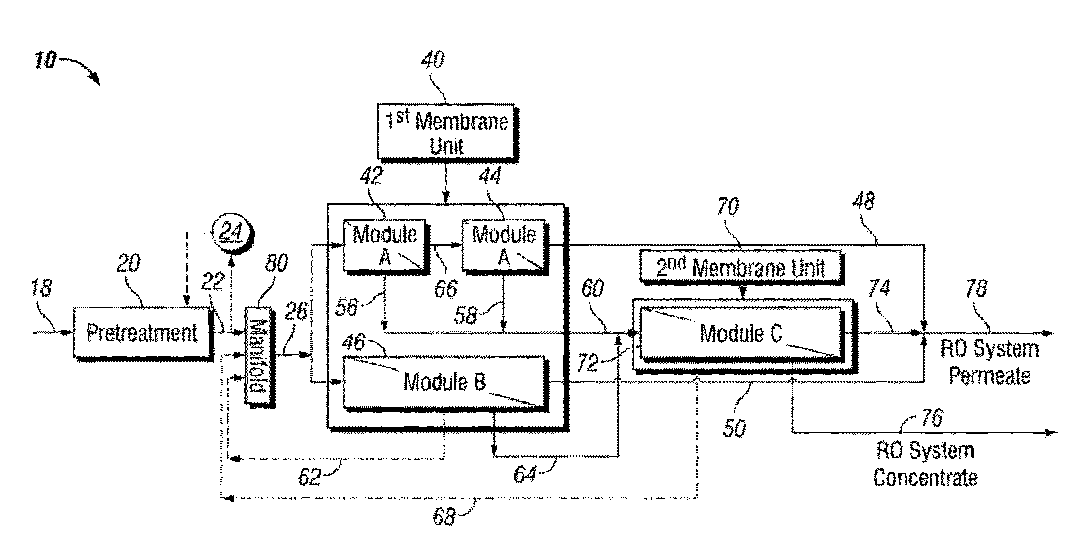
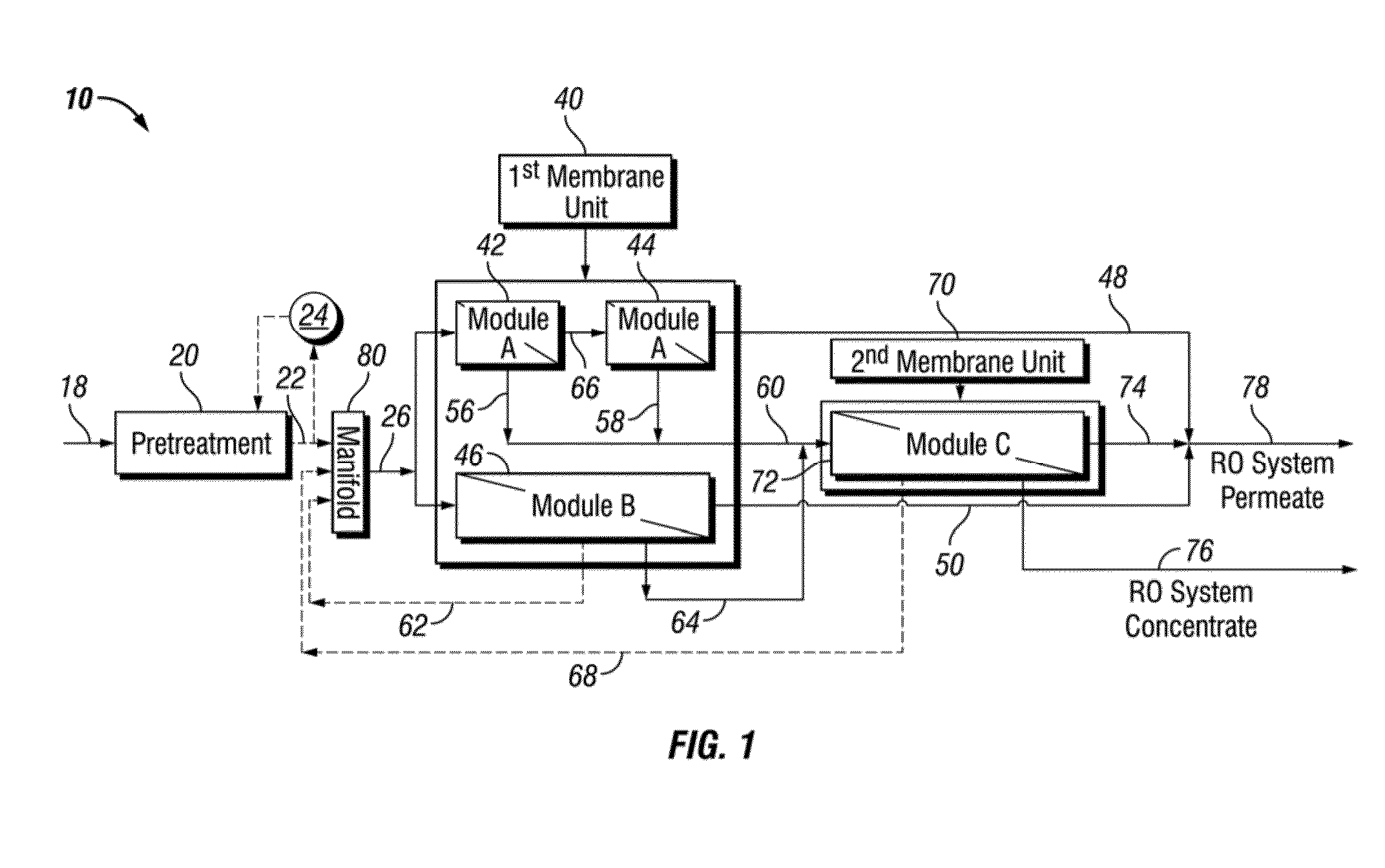
[0116]Produced water is treated to remove gas, oil, and larger particles. The produced water is then partially softened, after which antiscalant is added to the partially softened water, and the partially softened water is then run through a reverse osmosis system. The reverse osmosis system may include one or more reverse osmosis modules. In an embodiment of the invention, two RO modules are used. In the case of using more than one RO modules, the reject water from the second RO modules may be recycled back into the influx of the first RO module. In another embodiment, the RO module includes reverse osmosis / nanofiltrate (RO / NF) membranes.

[0117]In this example, produced water from one type of reservoir consists of approximately 3,800 ppm of total hardness. Partial water softening followed by one or more RO membranes yields purified water having a hardness of less than 1.0 ppm, to meet steamflooding requirements. Embodiments of the disclosure use The RO membranes may be high recovery...

example 3

[0118]Produced water is treated to remove gas, oil, and larger particles. This process can include a clarification module followed by flotation units and filters. It is anticipated that a flotation unit can remove up to about 95% of oil and some of the gases, such as hydrogen sulfide and carbon dioxide, from water. An ultra-filtration unit, such as a ceramic UF membrane unit may also be used prior to the softening and RO system of the current disclosure. The water may also be heated or cooled prior to entering the softening system (chemical or softener based), or after going through the softening system and before entering the RO system. For example, the water may be cooled to lower than 113° F. (45° C.) prior to going through the RO system but after going through the softening system. As another example, the water may be heated prior to chemical softening methods. After pretreatment, the produced water is then partially softened in a partial softening unit. The unit may use chemica...


PUM

PropertyMeasurementUnit
sizeaaaaaaaaaa
pHaaaaaaaaaa
pressureaaaaaaaaaa

Abstract

Produced water from a crude oil or natural gas production process is purified using a membrane purification system for petroleum production, agricultural, commercial and domestic uses. The produced water is pretreated to remove, at least, particulates and oil from the produced water. The minimally pretreated water is then purified in a membrane purification system that is operated at conditions such that membrane scaling is reduced or prevented. In particular, the membrane purification system is operated to maintain the turbidity of clarified water feed to the system or intermediate aqueous streams that are cascading through the membrane purification system. Ensuring that the turbidity of the reject streams generated in the membrane system are useful in achieving long membrane operating life.

Description

CROSS-REFERENCE TO RELATED APPLICATION[0001]The present application is a continuation-in-part application of and claims the benefit under 35 USC 120 of U.S. application Ser. No. 13 / 836,317, with a filing date of Mar. 15, 2013. This application also claims benefit under 35 USC 119 of US Provisional Patent Application No. 62 / 198,299 with a filing date of Jul. 29, 2015. This application claims priority to and benefits from the foregoing, the disclosures of which are incorporated herein by reference.TECHNICAL FIELD[0002]The present disclosure generally relates to system methods for purifying and clarifying water. In one embodiment, systems and methods are directed to purifying water with high total hardness levels produced from oil and gas operations to result in cleaner boiler or drinking quality water.BACKGROUND[0003]Crude oil and natural gas production often involves generating produced water along with the petroleum products. Reusing this water, either as part of the petroleum produ...

Claims


Application Information

Patent Timeline
Patent Type & Authority Applications(United States)
IPC IPC(8): C02F1/44C02F1/52C02F11/143
CPCB01D61/022B01D61/58C02F1/44C02F1/444C02F1/442C02F1/52C02F1/5236C02F1/441C02F2103/365B01D61/025B01D61/04C02F1/20C02F1/24C02F5/00C02F5/06C02F5/083C02F9/00E21B43/40B01D2311/25B01D2311/268B01D2317/025C02F2001/007C02F2001/425C02F2101/32C02F2103/10C02F2303/22C02F1/42C02F1/5245C02F1/66C02F11/14C02F2209/06C02F2209/11C02F11/143B01D61/026E21B43/35
Inventor TAO, FAN-SHENG TEDDYHOBBS, RONALD DAVIDCHEN, CHENGSUBRAHMANYAN, SUMITRA
Owner CHEVROU USA INC
Why Eureka
Try Eureka