Meta-material resonator antennas

a dielectric material and resonator technology, applied in the direction of resonant antennas, photomechanical devices, instruments, etc., can solve the problems of limited dras to simple structures, difficult fabrication of known dras, and limited dras

Active Publication Date: 2015-12-31
UNIVERSITY OF SASKATCHEWAN
View PDF27 Cites 55 Cited by
  • Summary
  • Abstract
  • Description
  • Claims
  • Application Information

AI Technical Summary

Problems solved by technology

While planar metal patch antennas can easily be produced in various complicated shapes by lithographic processes, DRAs have been mostly limited to simple structures (such as rectangular and circular / cylindrical shapes).
Indeed, fabrication difficulties have heretofore limited the wider use of DRAs, especially for high volume commercial applications
Fabrication of known DRAs can be particularly challenging as they have traditionally been made of high relative permittivity ceramics.
Ceramic-based DRAs can involve a complex fabrication process due in part to their three-dimensional structure.
Moreover, ceramics are naturally hard and difficult to machine.
Batch fabrication can require diamond cutting tools, which can wear out relatively quickly due to the abrasive nature of the ceramic materials.
In addition, ceramics are generally sintered at high temperatures in the range of 900-2000° C., further complicating the fabrication process, limiting the achievable element geometries, and possibly restricting the range of available materials for other elements of the DRA.
Array structures can be even more difficult to fabricate due to the requirement of individual element placement and bonding to the substrate.
Accordingly, they cannot easily be made using known automated manufacturing processes.
Further problems appear at millimetre-wave frequencies, where the dimensions of the DRA are reduced to the millimetre or sub-millimetre range, and manufacturing tolerances are reduced accordingly.
These fabrication difficulties have heretofore limited the wider use of DRAs, especially for high volume commercial applications.
However, these materials and approaches tend to be most suitable for realizing low-permittivity DRAs, which could limit the range of potential applications.

Method used


Image

  • Meta-material resonator antennas
  • Meta-material resonator antennas
  • Meta-material resonator antennas

Examples


Embodiment Construction

[0086]The use of polymer-based materials can dramatically simplify fabrication of dielectric resonator antenna elements and arrays, and may facilitate greater use of this class of antennas in commercial applications.

[0087]Described herein are compact radio frequency (RF) antennas and devices using non-traditional polymer-based materials, and methods for fabricating the same. The described compact RF antennas enable improved performance and increased functionality for various emerging wireless communication and sensor devices (e.g., miniature radios / transmitters, personal / wearable / embedded wireless devices, etc.), automotive radar systems, small satellites, RFID, sensors and sensor array networks, and bio-compatible wireless devices and biosensors). In particular, these polymer-based antenna devices may be referred to as polymer or polymer-based resonator antennas (PRAs).

[0088]Currently, one of the biggest obstacles to the continued miniaturization of RF wireless devices is antenna s...


PUM


Abstract

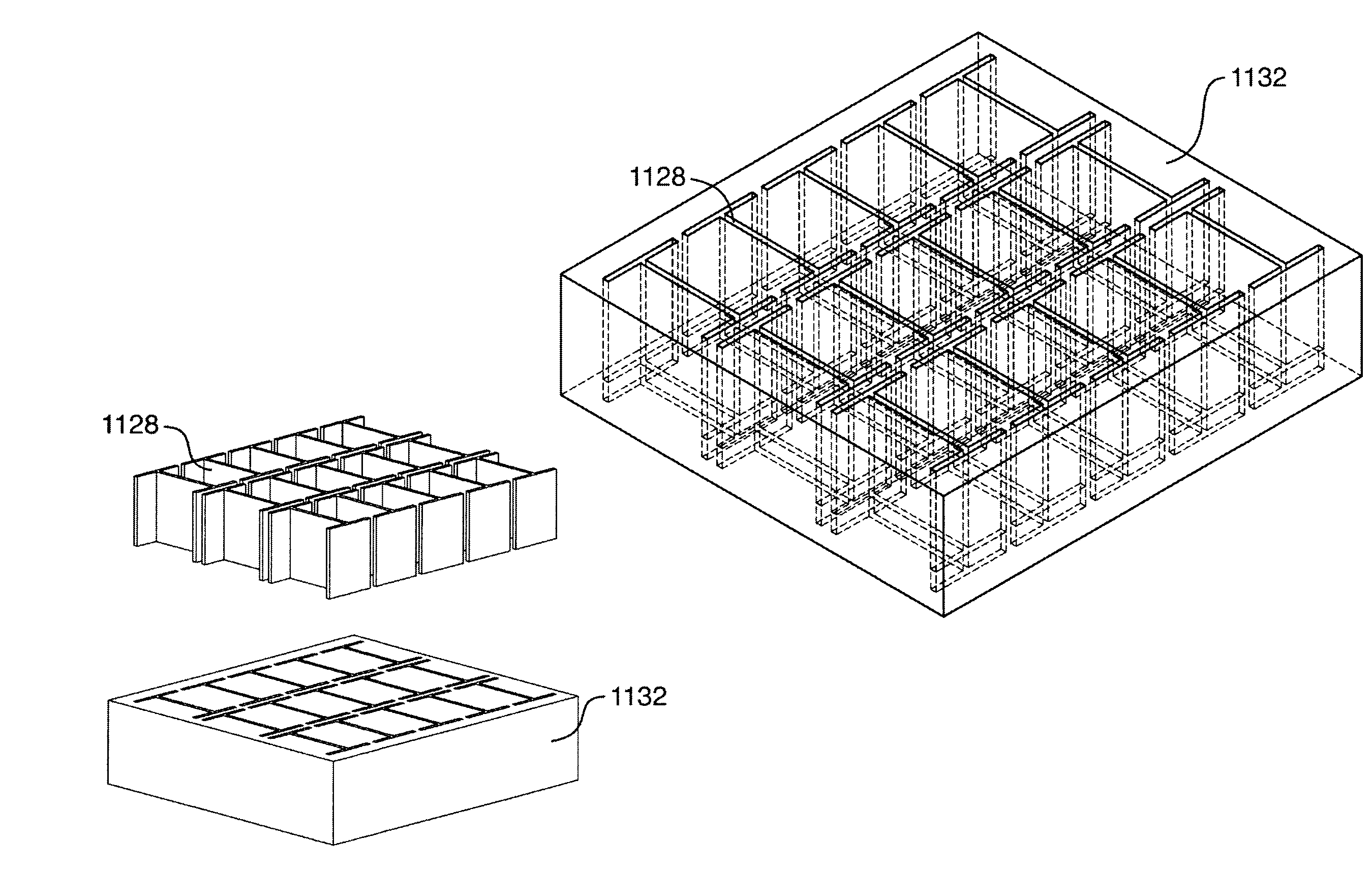
Antennas suitable for use in compact radio frequency (RF) applications and devices, and methods of fabrication thereof. Described are resonator antennas, for example dielectric resonator antennas fabricated using polymer-based materials, such as those commonly used in lithographic fabrication of integrated circuits and microsystems. Accordingly, lithographic fabrication techniques can be employed in fabrication. The antennas have metal inclusions embedded in the resonator body which can be configured to control electromagnetic field patterns, which serves to enhance the effective permittivity of the resonator body, while creating an anisotropic material with different effective permittivity and polarizations in different orientations.

Description

FIELD[0001]The embodiments described herein relate to microwave and radio frequency (RF) dielectric materials and devices, including antennas, and methods for fabricating the same. In particular, the described embodiments relate to dielectric materials containing metal inclusions and the use of these materials as dielectric resonator antennas.INTRODUCTION[0002]Microwave dielectric materials find widespread use in circuits and devices in the 1 to 100 GHz range. For example, high permittivity dielectric materials are employed as dielectric resonators (DRs) for use as frequency selective elements in oscillators and filters, and as radiating elements in antennas and antenna arrays.[0003]Recently, dielectric resonator antennas (DRAs) have attracted increased attention for miniaturized wireless and sensor applications at microwave and millimetre-wave frequencies. DRAs are three-dimensional structures with lateral dimensions that can be several times smaller than traditional planar metal “...

Claims


Application Information

Patent Timeline
Patent Type & Authority Applications(United States)
IPC IPC(8): H01Q9/04
CPCH01Q15/0066H01Q9/0485H01Q15/0086
Inventor TAYFEH ALIGODARZ, MOHAMMADREZARASHIDIAN, ATABAKKLYMYSHYN, DAVID
Owner UNIVERSITY OF SASKATCHEWAN
Why Eureka
Try Eureka