Cheek and lip expansion device and method

a technology of lip and cheek, which is applied in the field of dental surgery, can solve the problems of discomfort for patients, difficult to insert and remove, and cannot permit further manipulation of patients' lips or cheeks without causing pain, so as to facilitate insertion and maintenance, and facilitate insertion and removal.

Active Publication Date: 2016-01-14
ULTRADENT PROD INC
View PDF3 Cites 10 Cited by
  • Summary
  • Abstract
  • Description
  • Claims
  • Application Information

AI Technical Summary

Benefits of technology

[0008]Disclosed herein are cheek and lip retraction or expansion devices for use in dental procedures or other procedures requiring access to the oral cavity with minimal obstruction. Various features are disclosed which may provide collapsibility, ability to latch in a collapsed configuration, and easier insertion into a patient's mouth, (e.g., even allowing insertion with one hand). The device may include structural and / or curvature characteristics which help “pull” the device into a patient's mouth, facilitating easier insertion and maintenance within the mouth once installed.

Problems solved by technology

Various retraction devices exist, although these devices share certain problems.
They are often difficult to insert and remove, often requiring extensive time to insert and causing discomfort to the patient during insertion and removal.
They are generally uncomfortable to patients and can activate patient's pharyngeal reflexes (i.e., gag reflex).
In such cases, they do not permit further manipulation of the patient's lips or cheeks without causing pain.
In other cases, they include bulky lip retraction structures that can block access to tooth surfaces along the sides of a dental arch.

Method used


Image

  • Cheek and lip expansion device and method
  • Cheek and lip expansion device and method
  • Cheek and lip expansion device and method

Examples


Embodiment Construction

I. Introduction

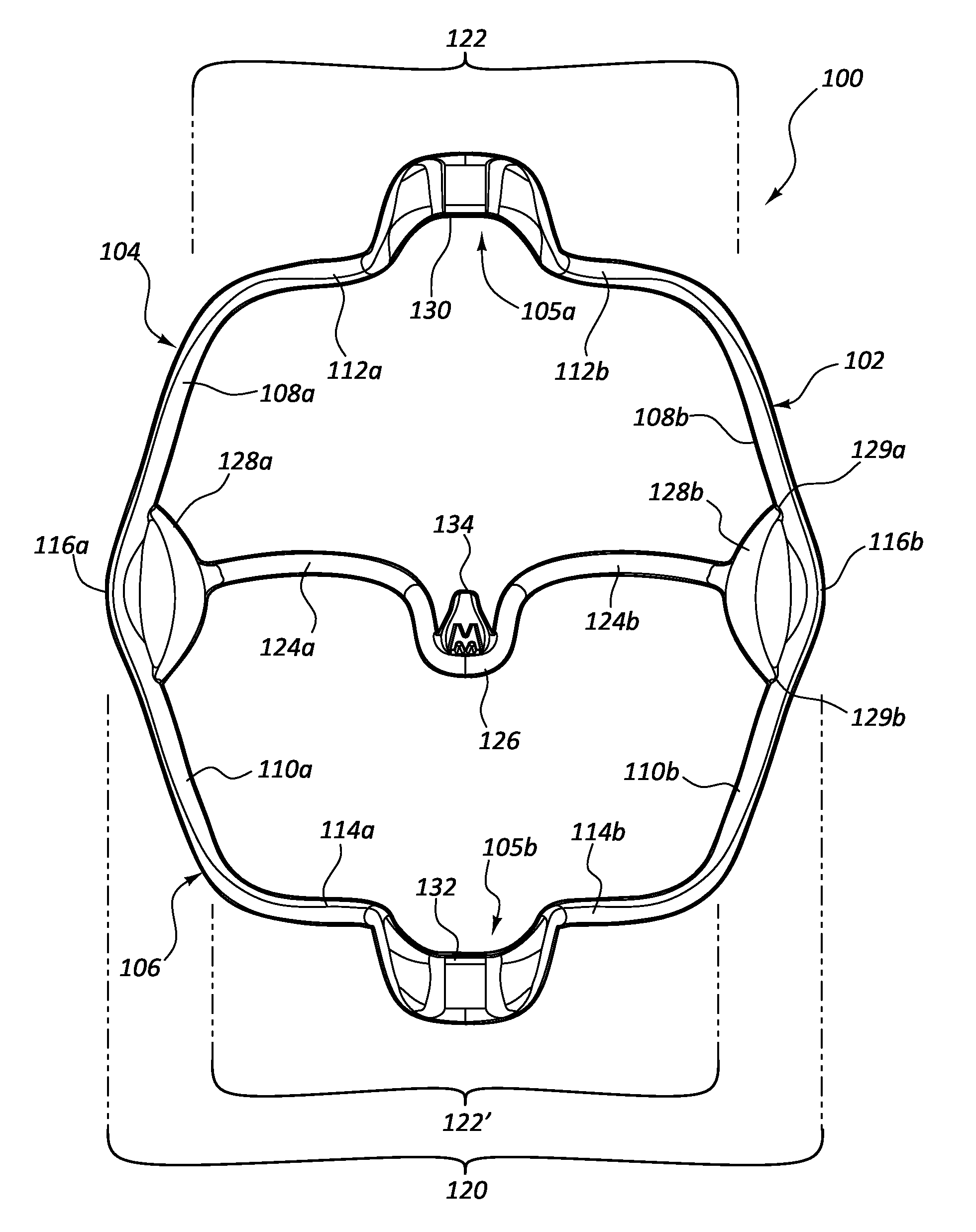
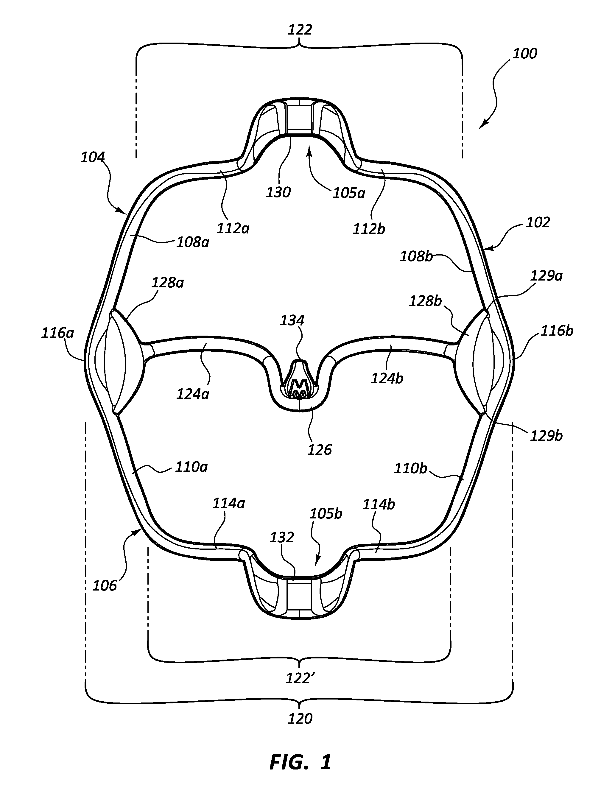
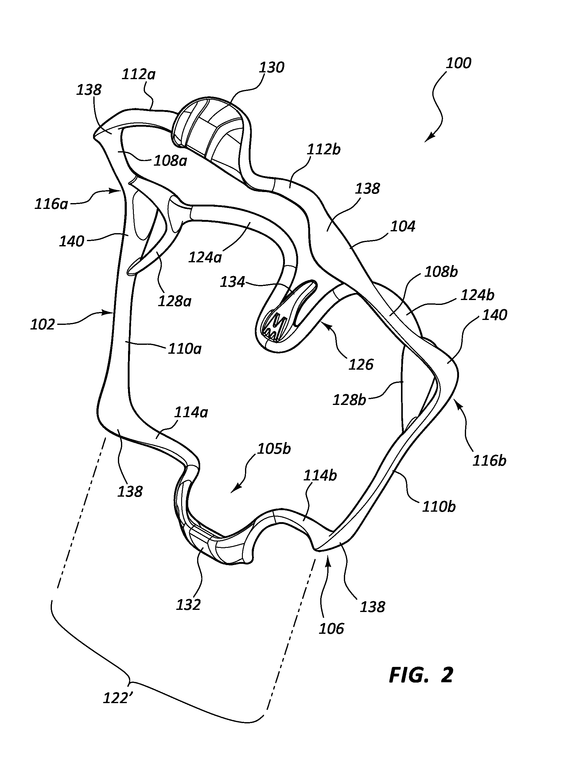
[0046]The invention generally relates to intra-oral cheek and lip expansion devices useful for expansion of soft oral tissues away from the dental arches, isolating one or more teeth from soft oral tissue and creating an enlarged working field. Such cheek and lip expansion devices may include a selectively collapsible and expandable flexible and resilient (e.g., spring-like) frame for insertion into an oral cavity. The collapsed configuration facilitates insertion into the mouth, while the expanded configuration, while positioned in the mouth, allows the frame to bear against and retract or displace soft oral tissue in multiple dimensions and thereby isolate one or more teeth from soft oral tissue and create an enlarged working field. For example, rather than moving the mandible down, the cheeks and lips may be displaced outward and forward in order to enlarge the working field, increasing space for the practitioner to work and / or visualize the teeth, gums, or other s...


PUM


Abstract

Cheek and lip expansion devices including an upper frame portion configured to extend about an upper dental arch, and a lower frame portion configured to extend about a lower dental arch. The upper and lower frame portions may each include first and second side members, each with anterior and posterior regions. An upper connecting member may extend between the anterior regions of the upper side members. A lower connecting member may extend between the anterior regions of the lower side members. The posterior regions of the upper and lower side members on respective sides of the frame are joined to one another to form a bendable radius that resists bending at a distinct point. The bendable radius on opposed sides permits the frame to be collapsed top to bottom. The frame may be collapsible side-to-side. A posterior crossbar may be provided extending between the posterior regions of the side members.

Description

CROSS-REFERENCE TO RELATED APPLICATION[0001]The present application is a continuation-in-part of U.S. patent application Ser. No. 14 / 776,867, filed Sep. 15, 2015, entitled CHEEK RETRACTOR DEVICE AND METHOD″, which is a 35 U.S.C §371 national stage application of PCT Application PCT / US14 / 28083, filed Mar. 14, 2014, entitled CHEEK RETRACTOR DEVICE AND METHOD″ which claims the benefit of U.S. Provisional Patent Application Ser. No. 61 / 789,929, filed Mar. 15, 2013, entitled “CHEEK RETRACTOR DEVICE AND METHOD”. The disclosure of each of the foregoing is incorporated by reference in its entirety.BACKGROUND[0002]1. The Field of the Invention[0003]The present invention is in the field of dentistry, particularly devices for isolating a patient's teeth from soft oral tissue and enlarging the working field for the practitioner.[0004]2. The Relevant Technology[0005]In certain procedures, particularly certain dental procedures, it can be helpful to retract soft oral tissue of the oral cavity fro...

Claims


Application Information

Patent Timeline
Patent Type & Authority Applications(United States)
IPC IPC(8): A61C5/14
CPCA61C5/14A61B1/24A61B17/02A61B1/32A61C5/90A61B13/00A61B17/0293A61B2017/00862A61B2560/0443
Inventor JESSOP, NEIL T.MCLEAN, BRUCE S.HINES, CRAIG
Owner ULTRADENT PROD INC
Why Eureka
Try Eureka