Cheek retractor device and method

a retractor device and retractor technology, applied in the field of dental surgery, can solve the problems of easy pushed out configurations of oral cavities, and achieve the effects of easy insertion into the patient's mouth, and convenient insertion and maintenan

Active Publication Date: 2016-01-28
ULTRADENT PROD INC
View PDF9 Cites 8 Cited by
  • Summary
  • Abstract
  • Description
  • Claims
  • Application Information

AI Technical Summary

Benefits of technology

[0007]The present invention is directed to cheek retraction devices for use in dental procedures or other procedures requiring access to the oral cavity. Various features are disclosed which may provide collapsibility, ability to latch in a collapsed configuration, and easier insertion into a patient's mouth, (e.g., even allowing insertion with one hand). The device may include structural and / or curvature characteristics which help “pull” the device into a patient's mouth, facilitating easier insertion and maintenance within the mouth once installed.
[0008]In an aspect, the cheek retraction device includes a selectively collapsible and expandable frame for insertion into an oral cavity. The collapsed configuration facilitates insertion into the oral cavity, while the expanded configuration while positioned in the oral cavity allows it to bear against and retract soft oral tissue so as to isolate one or more teeth from soft oral tissue and create an enlarged working field. The frame may include an upper frame element configured to bear against and retract soft oral tissue from one or more teeth of an upper dental arch when the frame is in an expanded configuration. Similarly, a lower frame element may be configured to bear against and retract soft oral tissue from one or more teeth of a lower dental arch when the frame is expanded. The upper and lower frame elements may each include left and right frame portions, wherein the upper and lower left frame portions are joined to one another to form a v-shaped hinge on one side of the frame, while the upper and lower right frame portions are joined to one another to form a v-shaped hinge on another side of the frame. The v-shaped hinges on opposed sides (and disposed at a posterior portion of the device) permit the upper and lower frame elements to be at least partially folded toward each other. A posterior width of the upper and lower frame elements as defined between the right and left frame portions adjacent the v-shaped hinges may be greater than an anterior width of the upper and lower frame elements.
[0009]Such a configuration provides a greater posterior width to the device than its anterior width, helping to pull the device into the oral cavity, rather than push it out. For example, other cheek retractors exhibit an oppositely configured wedge relationship, where the anterior dimensions of the device are greater than the posterior dimensions. Such configurations exhibit a tendency to be easily pushed out of the oral cavity, rather than maintained in the desired position.
[0010]In another aspect, the invention is directed to a cheek retractor device including a selectively collapsible and expandable frame for insertion into an oral cavity. The collapsed configuration facilitates insertion into the oral cavity, while the expanded configuration while positioned in the oral cavity allows it to bear against and retract soft oral tissue so as to isolate one or more teeth from soft oral tissue and create an enlarged working field. The frame may include an upper frame element configured to bear against and retract soft oral tissue from one or more teeth of an upper dental arch when the frame is in an expanded configuration. Similarly, a lower frame element may be configured to bear against and retract soft oral tissue from one or more teeth of a lower dental arch when the frame is expanded. The upper and lower frame elements may each include left and right frame portions wherein the upper and lower left frame portions are joined to one another to form a v-shaped hinge on one side of the frame, while the upper and lower right frame portions are joined to one another to form a v-shaped hinge on another side of the frame. The v-shaped hinges on opposed sides (and disposed at a posterior portion of the device) permit the upper and lower frame elements to be at least partially folded toward each other. A posterior frame element may be provided extending between the v-shaped hinges. The posterior frame element may include a v-shaped or u-shaped portion to permit the v-shaped hinges on opposed posterior sides of the frame to be at least partially collapsed towards one another so that the device is collapsible in a side-to-side dimension as well as an upper-to-lower dimension.
[0011]In another aspect, the invention is directed to a cheek retractor device including a selectively collapsible and expandable frame for insertion into an oral cavity. The collapsed configuration facilitates insertion into the oral cavity, while the expanded configuration while positioned in the oral cavity allows it to bear against and retract soft oral tissue so as to isolate one or more teeth from soft oral tissue and create an enlarged working field. The frame may include an upper frame element configured to bear against and retract soft oral tissue from one or more teeth of an upper dental arch when the frame is in an expanded configuration. Similarly, a lower frame element may be configured to bear against and retract soft oral tissue from one or more teeth of a lower dental arch when the frame is expanded. The upper and lower frame elements may each include left and right frame portions wherein the upper and lower left frame portions are joined to one another to form a v-shaped hinge on one side of the frame, while the upper and lower right frame portions are joined to one another to form a v-shaped hinge on another side of the frame. The v-shaped hinges on opposed sides (and disposed at a posterior portion of the device) permit the upper and lower frame elements to be at least partially folded toward each other. The frame may include an upper lip protecting member disposed on an anterior portion of the upper frame element that is configured to extend away from an oral cavity and over an upper lip. A lower lip protecting member may similarly be disposed on an anterior portion of the lower frame element in a manner to extend away from the oral cavity and over a lower lip. The lip protecting members may be selectively engagable with one another when the upper frame element is folded towards the lower frame element so as to latch the upper and lower frame elements together.
[0012]In another aspect, the invention is directed to a cheek retractor device including a selectively collapsible and expandable frame for insertion into an oral cavity. The collapsed configuration facilitates insertion into the oral cavity, while the expanded configuration while positioned in the oral cavity allows it to bear against and retract soft oral tissue so as to isolate one or more teeth from soft oral tissue and create an enlarged working field. The frame may include an upper frame element configured to bear against and retract soft oral tissue from one or more teeth of an upper dental arch when the frame is in an expanded configuration. Similarly, a lower frame element may be configured to bear against and retract soft oral tissue from one or more teeth of a lower dental arch when the frame is expanded. The upper and lower frame elements may each include left and right frame portions wherein the upper and lower left frame portions are joined to one another to form a v-shaped hinge on one side of the frame, while the upper and lower right frame portions are joined to one another to form a v-shaped hinge on another side of the frame. The v-shaped hinges on opposed sides (and disposed at a posterior portion of the device) permit the upper and lower frame elements to be at least partially folded toward each other. A posterior frame element may extend between the v-shaped hinges on opposed sides of the frame, and a selectively removable tongue guard may be provided that is selectively coupleable to the posterior frame element to allow attachment or removal of the tongue guard.

Problems solved by technology

Such configurations exhibit a tendency to be easily pushed out of the oral cavity, rather than maintained in the desired position.

Method used


Image

  • Cheek retractor device and method
  • Cheek retractor device and method
  • Cheek retractor device and method

Examples


Embodiment Construction

[0026]I. Introduction

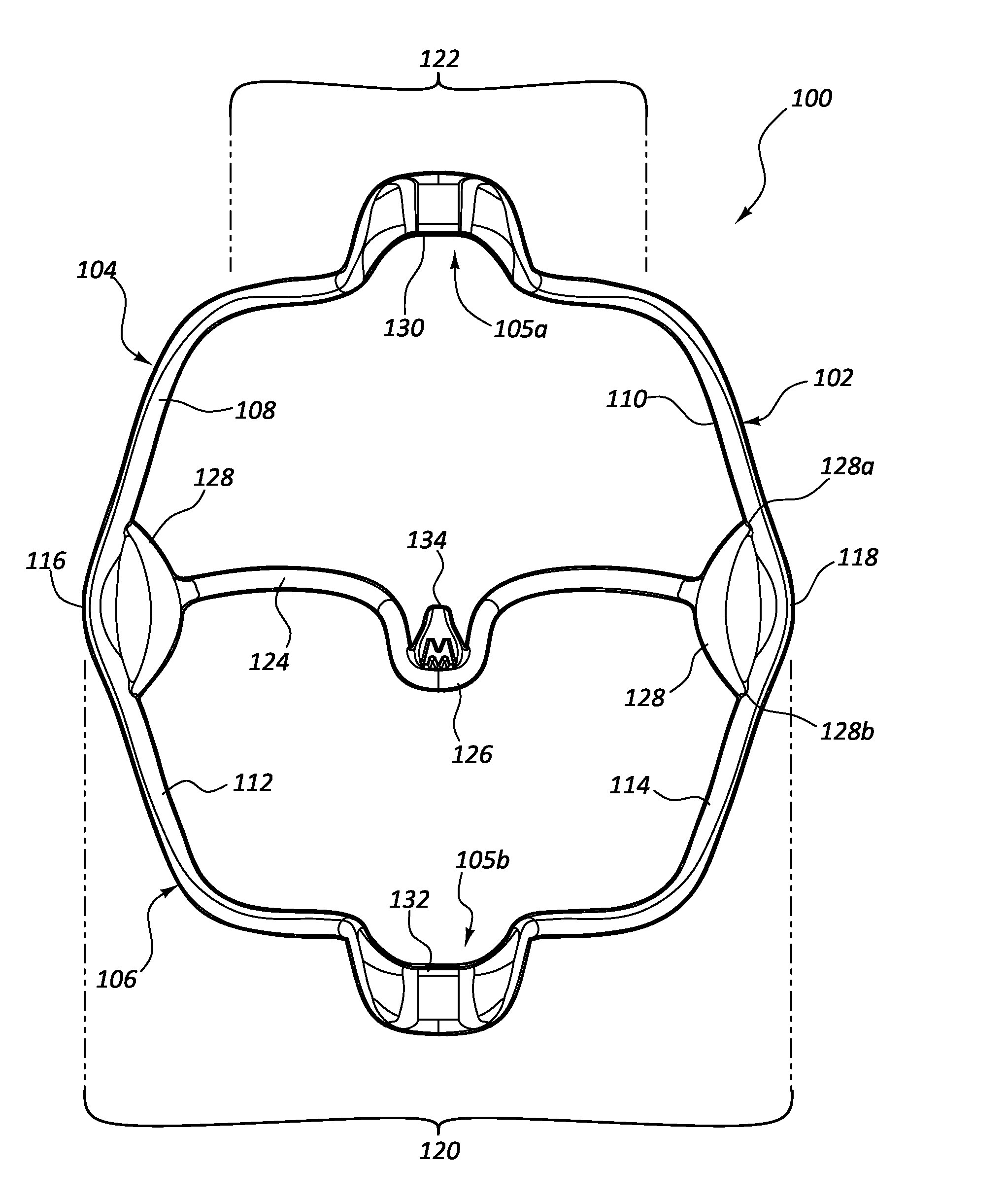
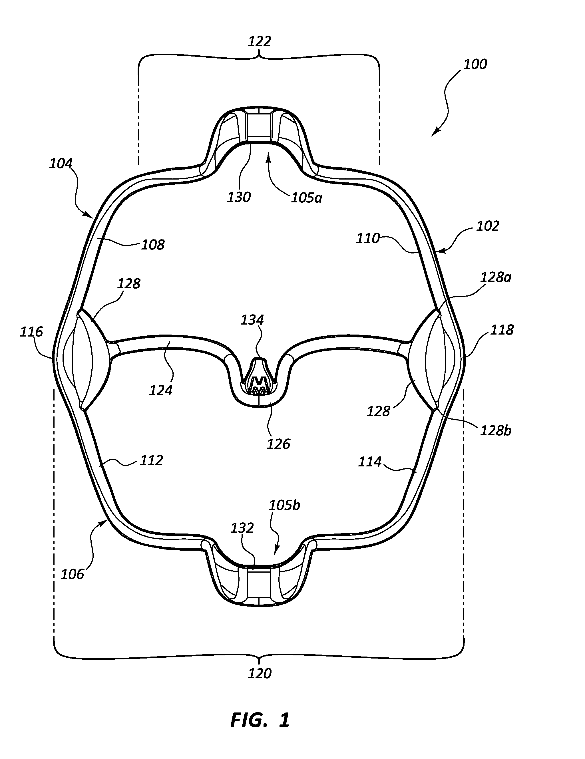
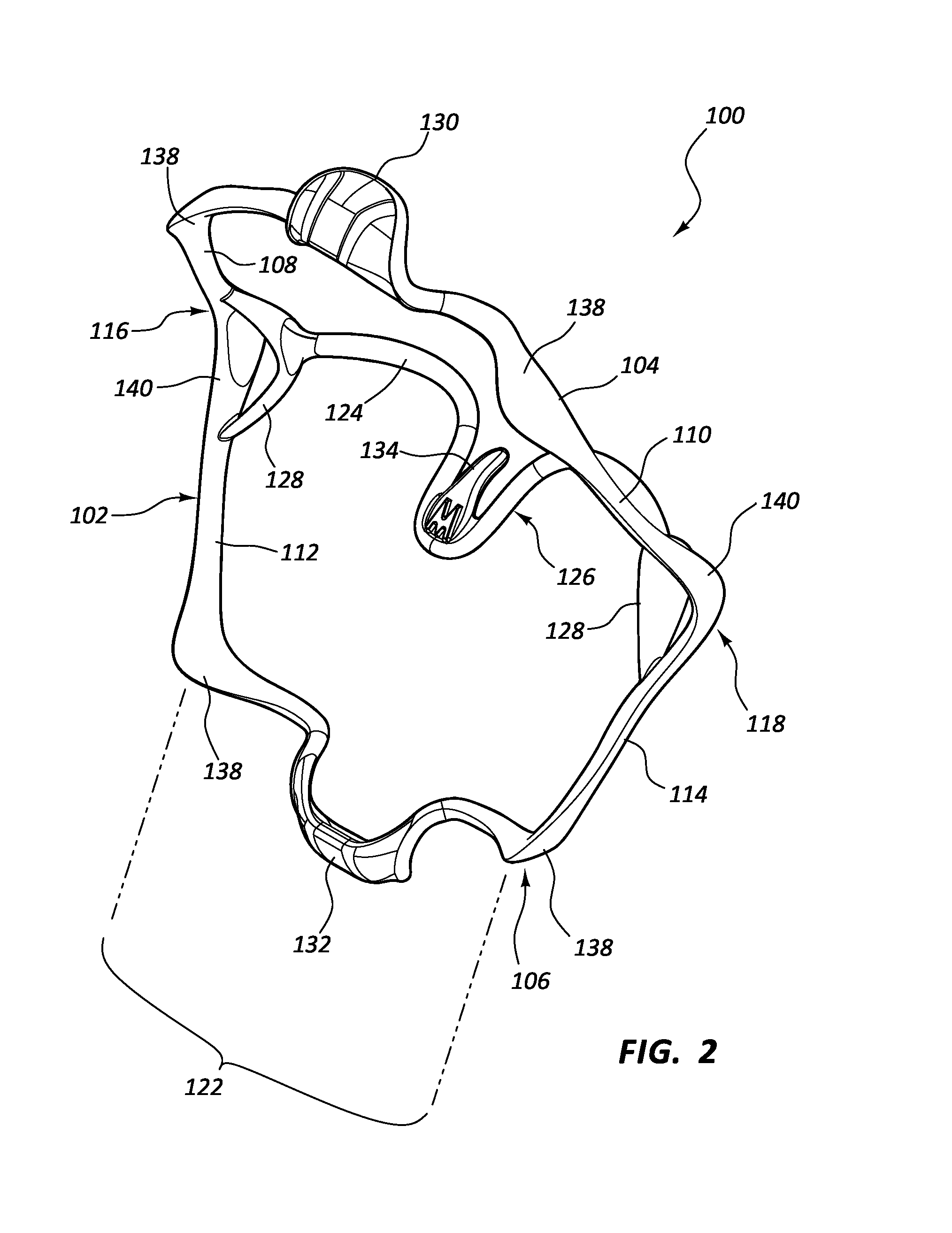
[0027]The invention generally relates to cheek retractor devices useful for isolating one or more teeth from soft oral tissue and creating an enlarged working field. Such cheek retractor devices may include a selectively collapsible and expandable frame for insertion into an oral cavity. The collapsed configuration facilitates insertion into the oral cavity, while the expanded configuration, while positioned in the oral cavity, allows the frame to bear against and retract soft oral tissue so as to isolate one or more teeth from soft oral tissue and create an enlarged working field.

[0028]The frame may include an upper frame element configured to bear against and retract soft oral tissue from one or more teeth of an upper dental arch when the frame is in an expanded configuration. Similarly, a lower frame element may be configured to bear against and retract soft oral tissue from one or more teeth of a lower dental arch when the frame is expanded. The upper and lo...


PUM


Abstract

Cheek retraction devices including an upper frame element configured to bear against and retract soft oral tissue from one or more teeth of an upper dental arch, a lower frame element configured to bear against and retract soft oral tissue from one or more teeth of a lower dental arch. The upper and lower frame elements may each include left and right frame portions wherein the upper and lower left frame portions are joined to one another to form a v-shaped hinge on one side of the frame, while upper and lower right frame portions are joined to one another to form a v-shaped hinge on another side of the frame. The v-shaped hinges on opposed sides permit the upper and lower frame elements to be at least partially folded toward each other. A posterior frame element may be provided extending between the v-shaped hinges.

Description

CROSS-REFERENCE TO RELATED APPLICATION[0001]The present application claims the benefit of U.S. Patent Application Ser. No. 61 / 789,929, filed Mar. 15, 2013, entitled “CHEEK RETRACTOR DEVICE AND METHOD”, the disclosure of which is incorporated by reference in its entirety.BACKGROUND[0002]1. The Field of the Invention[0003]The present invention is in the field of dentistry, particularly cheek retractor devices for use in isolating a patient's teeth and enlarging the working field for the practitioner.[0004]2. The Relevant Technology[0005]In certain procedures, particularly certain dental procedures, it can be helpful to retract soft oral tissue around the oral cavity, isolating these soft oral tissues (e.g., the cheeks and lips) so as to create an enlarged working field around the teeth and dental arches.[0006]Various retraction devices exist, although these devices share certain problems. They are often difficult to insert and remove, often requiring extensive time to insert and causi...

Claims


Application Information

Patent Timeline
Patent Type & Authority Applications(United States)
IPC IPC(8): A61C5/14A61B13/00A61B17/02
CPCA61C5/14A61B17/0293A61B2560/0443A61B2017/00862A61B13/00A61B1/24A61B17/02A61B1/32A61C5/90
Inventor JESSOP, NEIL T.MCLEAN, BRUCE S.HINES, CRAIG
Owner ULTRADENT PROD INC
Why Eureka
Try Eureka