
Zipper with stamped metal zipper teeth

a zipper tooth and metal technology, applied in the direction of snap fasteners, slide fasteners, press-button fasteners, etc., can solve the problems of zipper teeth with zipper teeth with #2 zipper teeth not meeting the needs of the industry, structural strength, and zipper teeth that break and are easily forced away from zipper tape, etc., to achieve high structural strength, prevent zipper teeth from breaking, and high structural strength

Inactive Publication Date: 2016-01-21
CHUNG ROGER C Y
View PDF13 Cites 6 Cited by
  • Summary
  • Abstract
  • Description
  • Claims
  • Application Information

AI Technical Summary

Benefits of technology

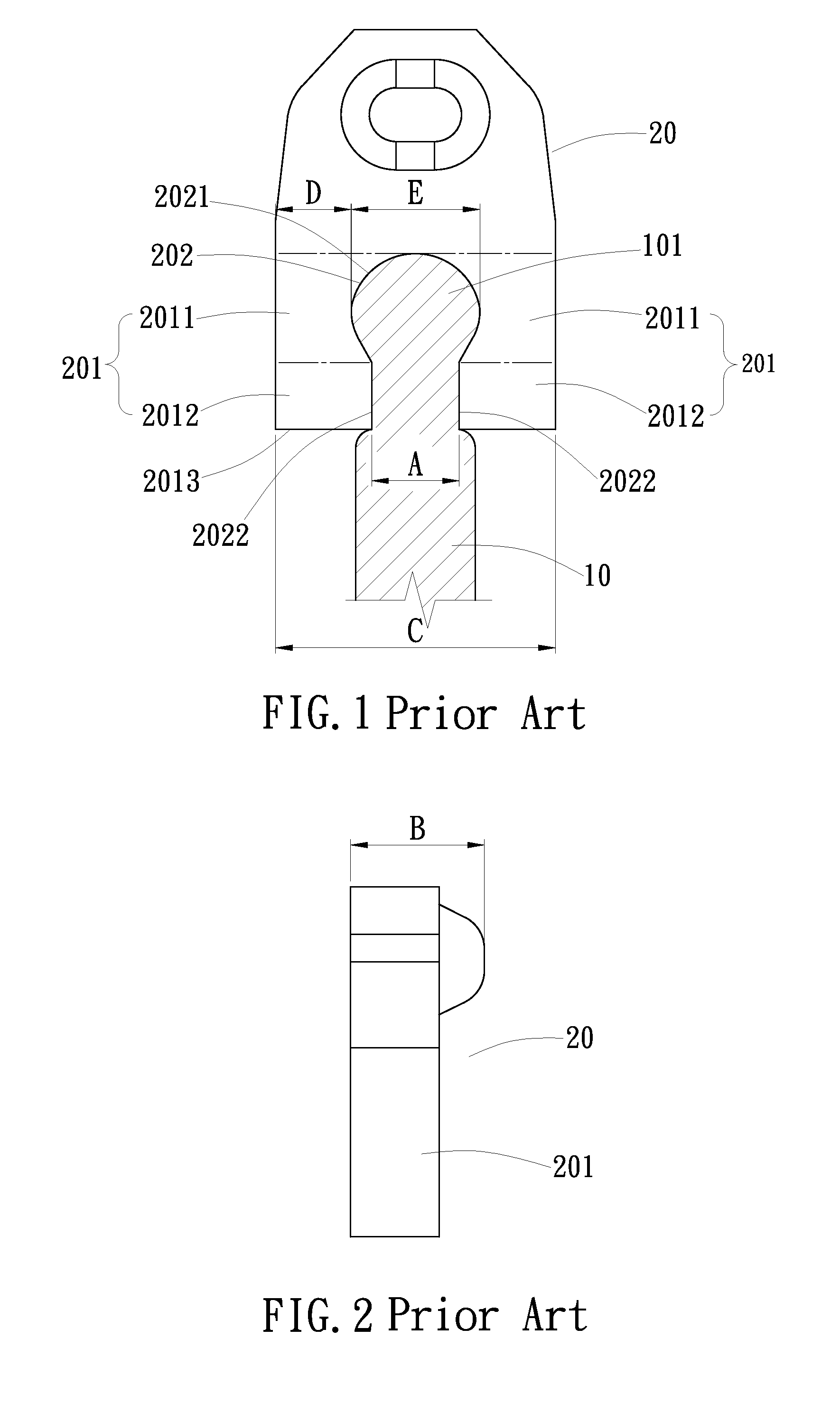
The present invention provides a zipper with stamped metal zipper teeth that can be made smaller than conventional metal zipper teeth to prevent breaking and ensure a high level of connection tightness between the zipper teeth and the zipper tape. The design of the zipper teeth allows for a high strength no matter they are made in any different specifications or even smaller than conventional #2 zipper teeth, preventing them from breaking easily and being tightly fastened to the zipper tapes. The mounting legs and retaining hole of each zipper tooth are specially constructed, allowing for a tight fastening of the zipper teeth to the rib of the zipper tape without vibration, even if the rib is elastically deformed. The relatively thicker rib is prohibited from passing through the relatively narrower gap between the inner walls of the rear ends of the mounting legs, ensuring the zipper teeth remain securely fastened to the rib.

Problems solved by technology

If the zipper tooth are smaller than the size #2, the structural strength will be insufficient, and the zipper tooth can break and be easily forced away from the zipper tape.
However, zippers with #2 zipper teeth cannot fully meet the needs of the industry.

Method used


Image

  • Zipper with stamped metal zipper teeth
  • Zipper with stamped metal zipper teeth
  • Zipper with stamped metal zipper teeth

Examples


Embodiment Construction

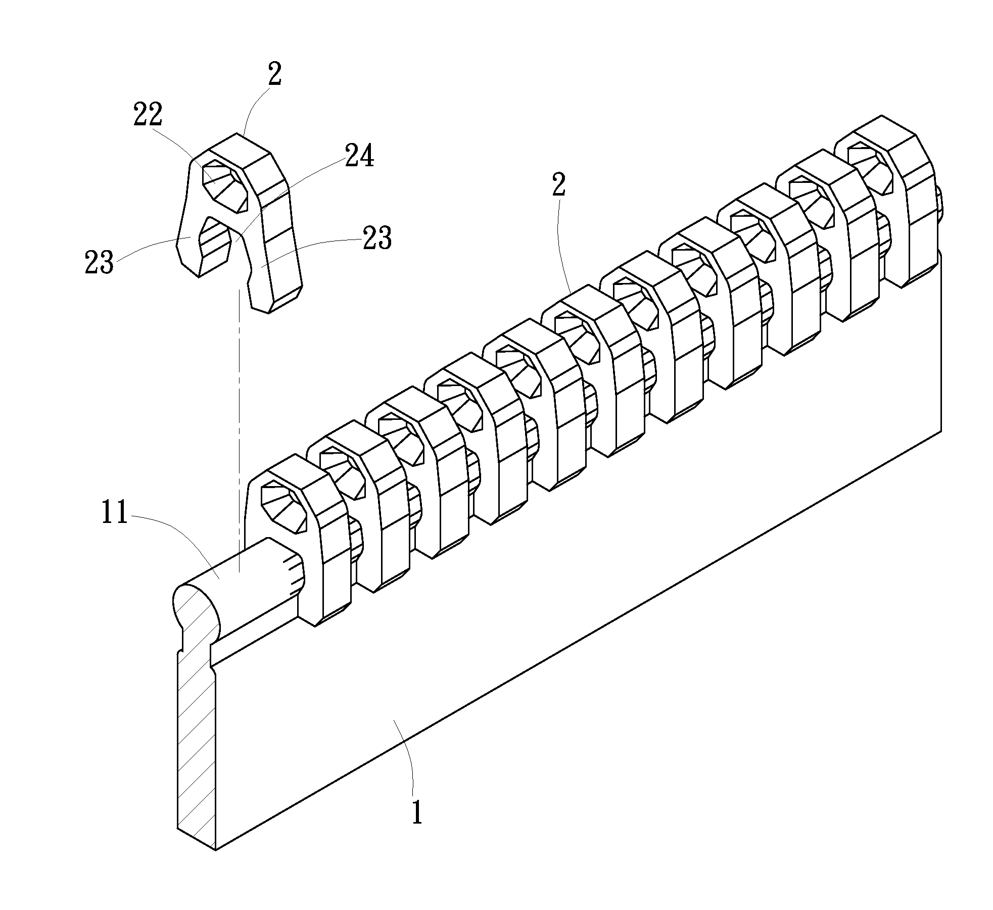
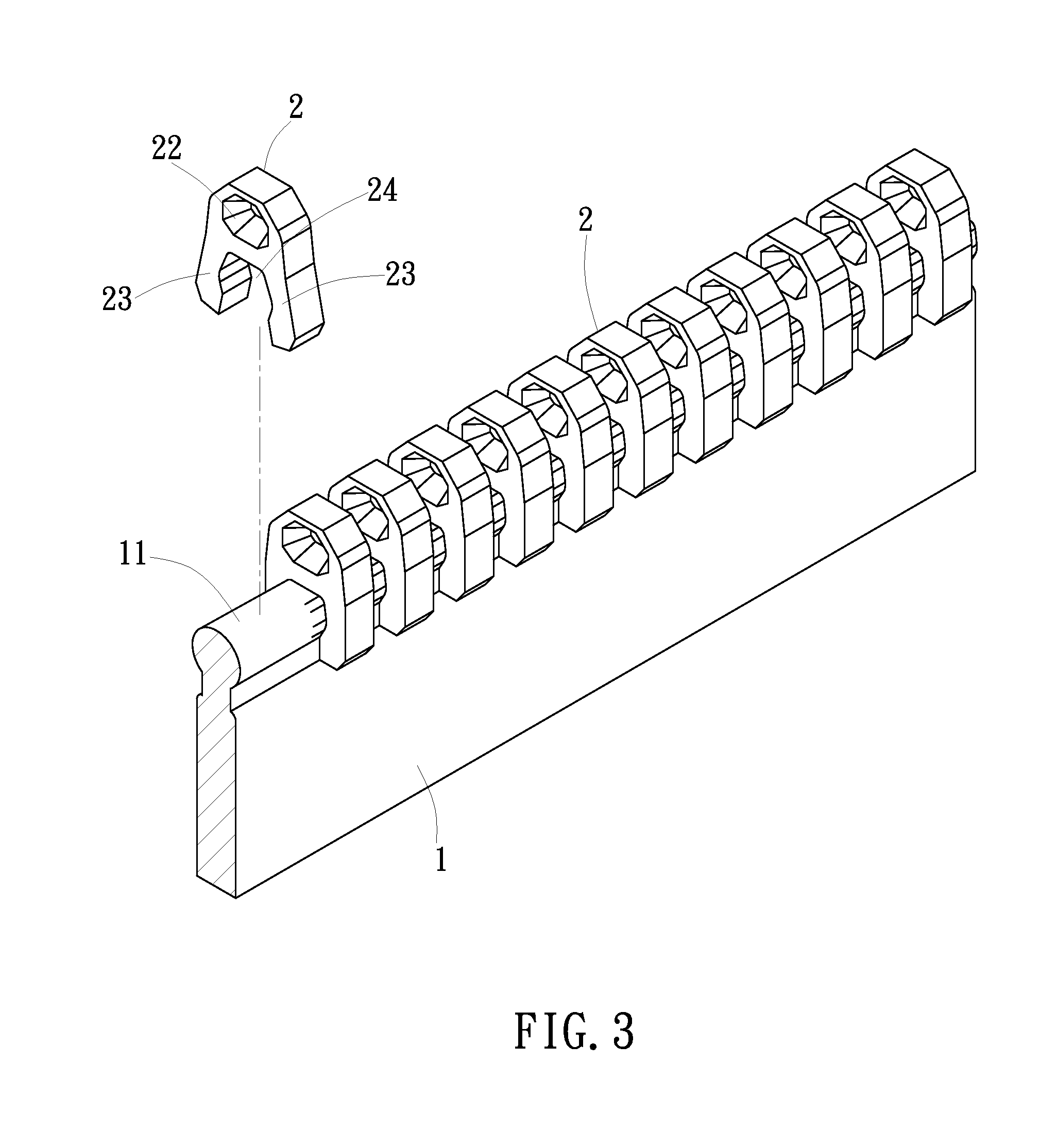
[0027]Referring to FIG. 3, a zipper with stamped metal zipper teeth in accordance with the present invention has stamped metal teeth mounted on each of two zipper tapes thereof. In a first embodiment of the present invention, the zipper comprises two zipper tapes 1, and a plurality of zipper teeth 2 mounted on one lateral side edge of each zipper tape 1 in a line. The zipper tapes 1 are fabric tapes, each having a rib 11 of circular cross section extending along one lateral side edge thereof for securing the zipper teeth 2. The zipper teeth 2 are engagement members made of metal by stamping for fastening to the ribs 11 of the zipper tapes 1, as shown in FIG. 3 and FIG. 4. Each zipper tooth 2 comprises a polygonal engagement protrusion 21 located on one side of a front end thereof (see FIG. 7), and a polygonal engagement recess 22 located on an opposite side of the front end. When the two zipper tapes 1 are driven by a sliding member (zipper slider) to move toward each other, the eng...


PUM


Abstract

A zipper with stamped metal zipper teeth includes two zipper tapes each having a rib at one lateral side thereof, and metal zipper teeth mounted at the rib of each zipper tape. Each zipper tooth has two mounting legs located at the rear end thereof and clamped on the rib. The ratio between the width of each zipper tooth and the gap between the mounting legs of each zipper tooth and the ratio between the combined height of each zipper tooth and the associated engagement protrusion and the gap between the mounting legs of each zipper tooth are in respective predetermined ranges so that the zipper teeth are stronger or even smaller than conventional #2 zipper teeth and have a tight connection between the zipper teeth and the zipper tape.

Description

BACKGROUND OF THE INVENTION[0001](a) Field of the Invention[0002]The present invention relates to zip fasteners and more particularly to a zipper with stamped metal zipper teeth. The zipper teeth are designed to have a high strength and can be made relatively small, preventing zipper teeth breaking and assuring a high level of connection tightness between the zipper teeth and the zipper tape.[0003](b) Description of the Prior Art[0004]Conventional stamped metal zipper teeth for zippers are classified by size in #2, #3, #4, #5, #8, #10, wherein #2 is the smallest size. According to today's technology and zipper tooth structure, zipper teeth must be no smaller than the size #2 so that zipper teeth can be strong enough for tightly fastening to a zipper tape. If the zipper tooth are smaller than the size #2, the structural strength will be insufficient, and the zipper tooth can break and be easily forced away from the zipper tape. However, zippers with #2 zipper teeth cannot fully meet ...

Claims


Application Information

Patent Timeline
Patent Type & Authority Applications(United States)
IPC IPC(8): A44B19/06A44B19/40
CPCA44B19/403A44B19/06
Inventor CHUNG, ROGER, C., Y.
Owner CHUNG ROGER C Y
Learn More