Compact hidden bearing structure for drawer

A compact and drawer technology, applied in drawers, applications, household appliances, etc., can solve the problem of low utilization of the internal space of the drawer, and achieve the effect of improving the user experience, improving the stability of the storage, and improving the compactness of the connection

Pending Publication Date: 2021-01-15
GUANGDONG DTC HARDWARE PRECISION MFG CO LTD
View PDF1 Cites 0 Cited by
  • Summary
  • Abstract
  • Description
  • Claims
  • Application Information

AI Technical Summary

Problems solved by technology

[0003] The purpose of the present invention is to provide a compact concealed storage structure for drawers to overcome the disadvantages of the prior art that the size of the drawer is fixed, and only a single-sized container can be concealed, and the utilization rate of the inner space of the drawer is low. place

Method used


Image

  • Compact hidden bearing structure for drawer
  • Compact hidden bearing structure for drawer
  • Compact hidden bearing structure for drawer

Examples


no. 1 example

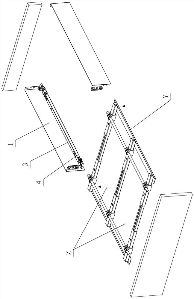
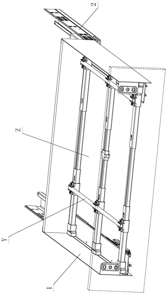
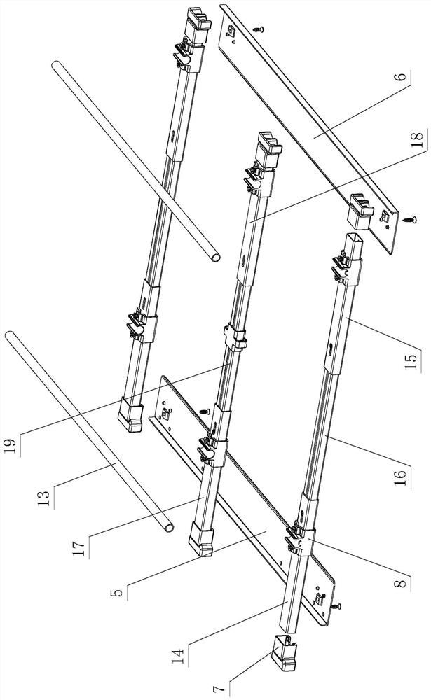
[0036] see Figure 1-Figure 10, the drawer uses a compact concealed storage structure, including side panels 1 and slide rail assemblies 2 arranged on the left and right, left and right support parts 3 and There is a relying part 4; the side plate 1 is detachably installed on the slide rail assembly 2, and when the two are assembled, the slide rail assembly 2 leans on the inner side of the relying part 4; between the left and right supporting parts A receiving device Y is provided, and the receiving device Y includes a left base 5, a right base 6 and a telescopic rod assembly; the left base 5 is at least supported on the left supporting part 3, and the right base 6 is at least supported on the On the right supporting part, the two ends of the telescopic rod assembly are respectively provided with positioning pieces 7, and are respectively fixed or longitudinally slid on the left base 5 and the right base 6 through the positioning pieces 7, wherein the two ends of the telescopi...

no. 2 example

[0052] see Figure 11 , the drawer uses a compact concealed storage structure, which is different from the first embodiment in that: the two ends of the telescopic rod assembly are respectively positioned and socketed on the socket part 9, and the two ends are directly supported by the socket part 9 respectively. On the slide rail assembly 2; wherein, the distance X is formed between the two ends of the telescopic rod assembly and the slide rail assembly 2 respectively through the socket part 9; when the slider 8 slides to a certain position, the limit acts on the inside of the socket part 9 , and at least part of it extends into the distance X, and is located above the slide rail assembly 2 .

[0053] Other unmentioned parts are the same as the first embodiment.


PUM


Abstract

The invention discloses a compact hidden bearing structure for a drawer. The structure comprises left and right side plates and left and right sliding rail assemblies, a left supporting part and a right supporting part are arranged on the lower portions of the left and right side plates respectively, and leaning parts are arranged on the left and right supporting parts respectively; the side plates are detachably arranged on the sliding rail assemblies, and when the side plates are assembled, the sliding rail assemblies lean against the inner sides of the leaning parts; a bearing device is arranged between the left supporting part and the right supporting part and comprises a left base, a right base and a telescopic rod assembly; and the left base is at least supported on the left supporting part, the right base is at least supported on the right supporting part, positioning pieces are arranged at the two ends of the telescopic rod assembly respectively, the telescopic rod assembly isfixed or longitudinally slides on the left base and the right base through the positioning pieces respectively, and the two ends of the telescopic rod assembly are spaced from the left base, the rightbase and/or the sliding rail assemblies through the positioning pieces correspondingly. Through the improvement of the structure, the practicability is high.

Description

technical field [0001] The invention relates to a compact concealed receiving structure for a drawer. Background technique [0002] The Chinese patent document number is CN111086803A, which discloses a drawer-type concealed trash can on May 1, 2020, which includes a trash can, a flat panel, a drawer guide rail and a connecting device, and the connecting device is either an L-shaped corner code or a wooden strip. It is said that the above-mentioned structure combines the trash can, flat panel and drawer guide rails into one. Usually the trash can is hidden in the vacant space under the furniture floor, and it is pulled out when it is needed, which eliminates the stumbling and unsightlyness of the trash can placed in the room Two big disadvantages; however, the size of the space in the kitchen is different, and the size of the drawers is designed according to the space in the kitchen. The size of the trash can is concealed, and its use is limited. At the same time, the trash...

Claims


Application Information

Patent Timeline
Patent Type & Authority Applications(China)
IPC IPC(8): A47B88/40A47B88/407A47B88/90A47B88/919B65F1/14
CPCA47B2210/09A47B88/40A47B88/407A47B88/90A47B88/919A47B88/941B65F1/141
Inventor 伍志勇
Owner GUANGDONG DTC HARDWARE PRECISION MFG CO LTD
Why Eureka
Try Eureka