
Assembly for sealing a gap between components of a turbine engine

a technology for turbine engines and components, applied in the field of turbine engines, can solve the problems of reducing the sealing effectiveness of rope seals and difficult positioning

Active Publication Date: 2016-01-21
RAYTHEON TECH CORP
View PDF4 Cites 6 Cited by
  • Summary
  • Abstract
  • Description
  • Claims
  • Application Information

AI Technical Summary

Benefits of technology

The invention provides an assembly for a turbine engine that includes a seal assembly. The seal assembly includes a rope seal and a clip that attaches the rope seal to a component of the engine. The seal is used to seal gaps between different components of the engine. The technical effect of this invention is to improve the performance and efficiency of turbine engines by reducing air leakage and improving sealing between components.

Problems solved by technology

Such a rope seal is relatively flexible and therefore may be difficult to locate during turbine engine assembly.
The dislocated rope seal may become pinched between the cases, which may damage and / or reduce the sealing effectiveness of the rope seal.

Method used


Image

  • Assembly for sealing a gap between components of a turbine engine
  • Assembly for sealing a gap between components of a turbine engine
  • Assembly for sealing a gap between components of a turbine engine

Examples


Embodiment Construction

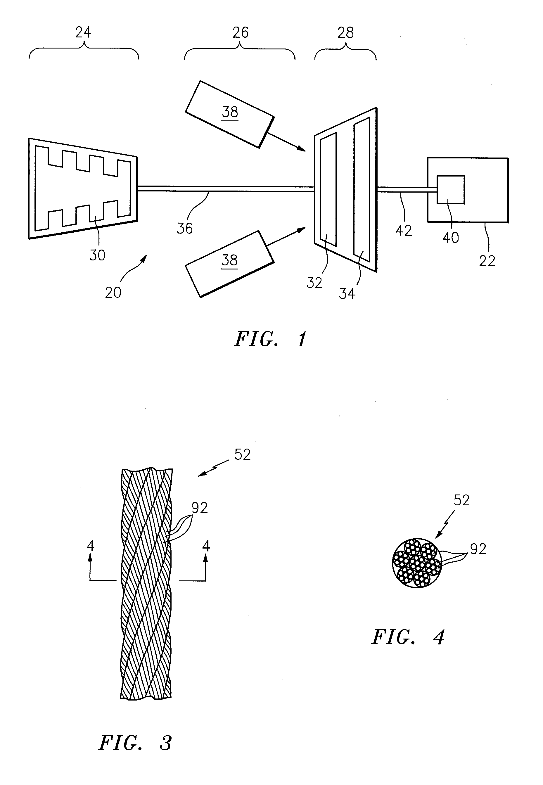
[0029]FIG. 1 is a schematic illustration of an industrial turbine engine 20 configured with an electrical generator 22. The turbine engine 20 may be configured for a land based installation, and includes a compressor section 24, a combustor section 26 and a turbine section 28. The compressor section 24 includes at least one compressor rotor 30. The turbine section 28 includes one or more turbine rotors 32 and 34. The compressor rotor 30 is connected to and driven by the turbine rotor 32 through an engine shaft 36. The combustor section 26 includes one or more combustors 38, which are arranged about the engine shaft 36. The combustors 38 are fluidly coupled between the compressor section 24 and the turbine section 28. The electrical generator 22 includes at least one generator rotor 40, which is connected to and driven by the turbine rotor 34 through a shaft 42.

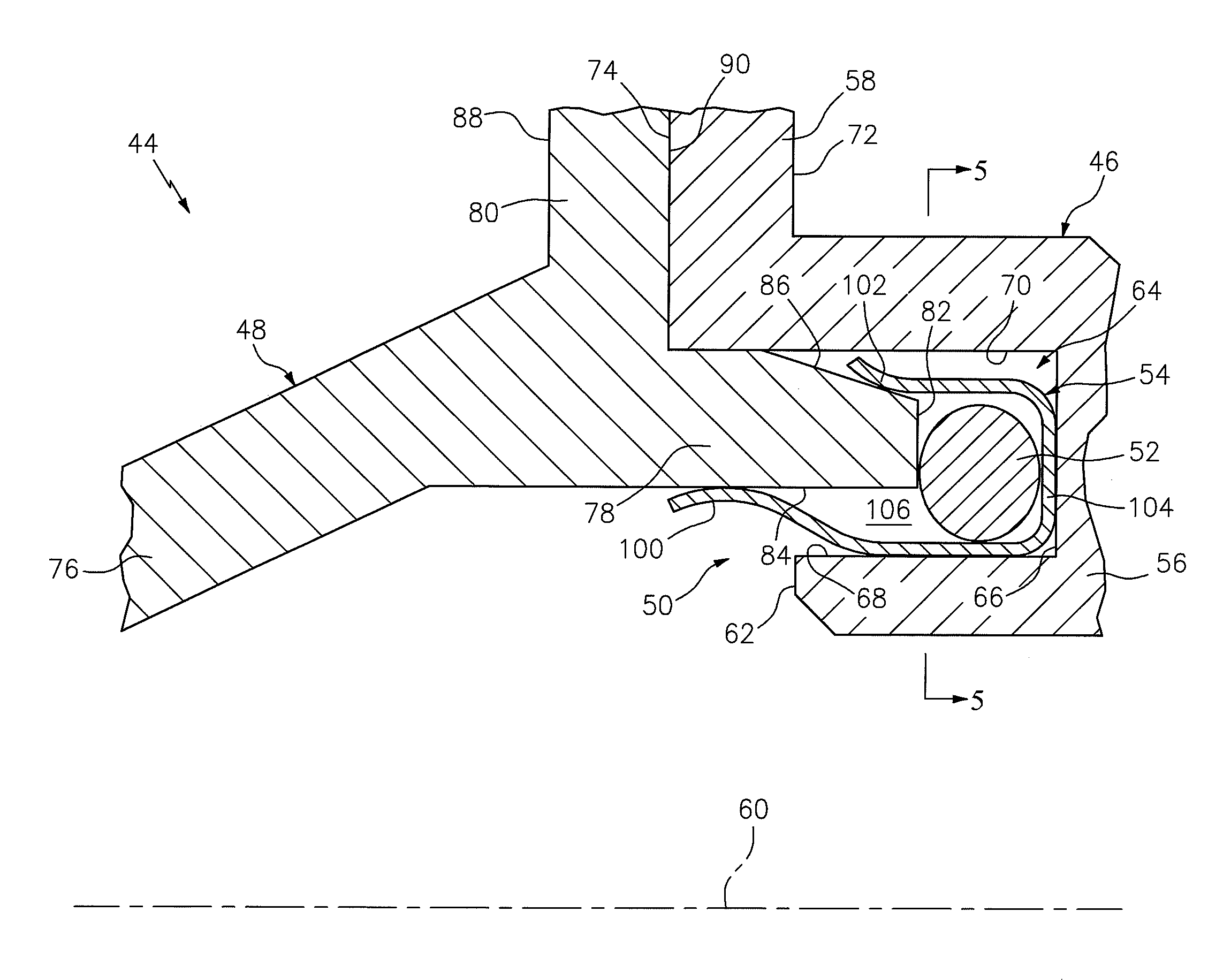
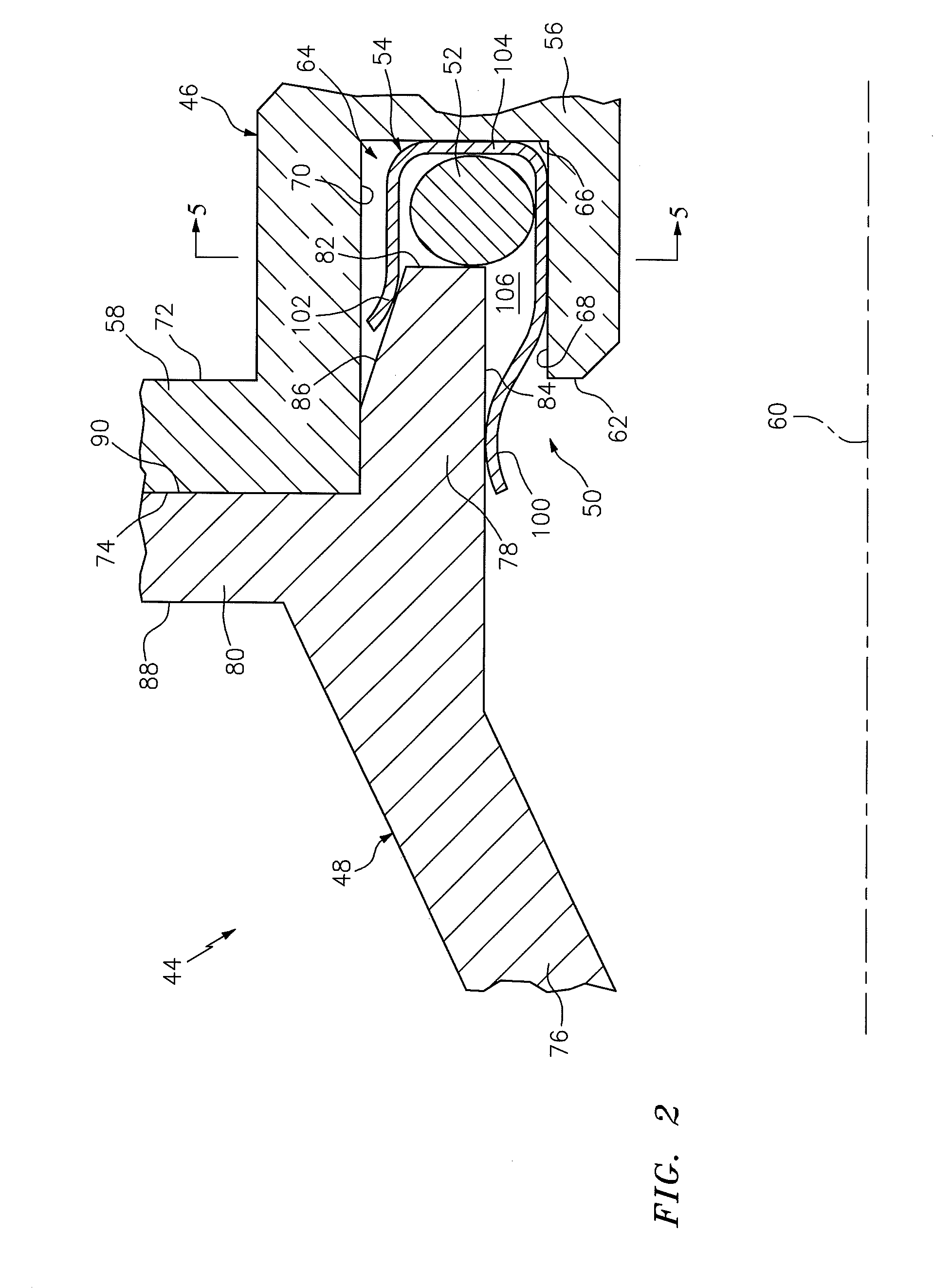
[0030]FIG. 2 is a side sectional illustration of a portion of an assembly 44 for the turbine engine 20 of FIG. 1. The assemb...


PUM


Abstract

An assembly for a turbine engine includes a turbine engine first component, a turbine engine second component and a seal assembly. The first component includes a groove and a groove surface. The second component includes a tongue that extends into the groove to a tongue surface. The seal assembly at least partially seals a gap between the groove surface and the tongue surface. The seal assembly includes a rope seal and a clip that attaches the rope seal to the tongue. The rope seal is arranged within the groove between the groove surface and the tongue surface.

Description

[0001]This application claims priority to U.S. Patent Appln. No. 61 / 770,162 filed Feb. 27, 2013.BACKGROUND OF THE INVENTION[0002]1. Technical Field[0003]This disclosure relates generally to a turbine engine and, more particularly, to an assembly for sealing a gap between components of a turbine engine.[0004]2. Background Information[0005]Various types of seals are known in the art for reducing air leakage between components of a turbine engine. A rope seal, for example, may be arranged to seal a gap between adjacent turbine engine cases.[0006]A typical rope seal is constructed from a plurality of metal wires that are woven together into a bundle. Such a rope seal is relatively flexible and therefore may be difficult to locate during turbine engine assembly. A portion of the rope seal, for example, may slip out of a locating groove in one of the turbine engine cases where the case is subject to vibrations and / or jarring movements. The dislocated rope seal may become pinched between t...

Claims


Application Information

Patent Timeline
IPC IPC(8): F01D11/00F01D25/26
CPCF05D2260/97F01D11/005F05D2240/55F05D2220/30F01D25/26F02C7/28F16J15/0812F05D2240/11F16J15/061
Inventor ROGERS, MARK J.DAVIS, TIMOTHY M.BROOMER, MARKWHITE, KEVIN W.MCGARRAH, CRAIGROY THILL, CARSON A.
Owner RAYTHEON TECH CORP
Learn More