

Experiment simulation device, system and preparation method for fine-bundle type fuel assembly
A technology of fuel assembly, experimental simulation, applied in the field of nuclear installations
- Summary
- Abstract
- Description
- Claims
- Application Information
AI Technical Summary
Problems solved by technology
Method used
Image

Examples
Embodiment 1
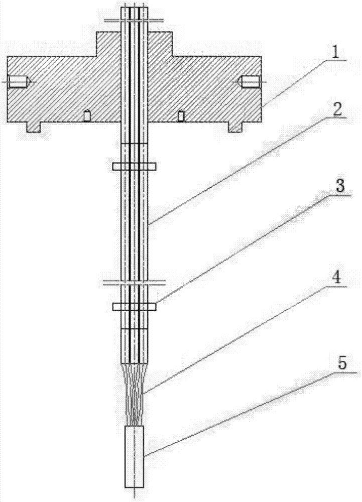
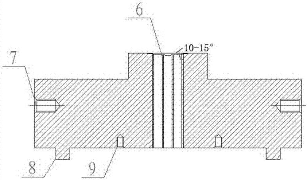
[0028] like figure 1 As shown, a thin rod bundle fuel assembly integrated experimental simulation device includes a conductive head 1, a heating element 2, and a conductive assembly connected in sequence from top to bottom; the conductive head 1 is provided with a through hole for connecting the heating element 2 6. The upper surface of the through hole 6 is an inverted tapered surface, and the bottom of the conductive head 1 is provided with an annular tenon surface 8, and there are two annular tenon surfaces 8, which are arranged symmetrically with the through hole 6 as the center.
Embodiment 2
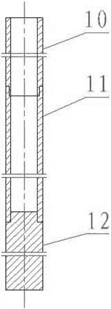
[0030] The heating element 2 is composed of a first cold section element 10, a hot section element 11, and a second cold section element 12 connected sequentially from top to bottom. Between the first cold section element 10 and the hot section element 11, the hot section element 11 and the second cold section element 12 are welded together.
[0031] The gap between the first cold segment element 10 and the hot segment element 11 is 0.5-0.8 mm, and the gap between the hot segment element 11 and the second cold segment element 12 is 0.5-0.8 mm.
[0032] The mechanical strength of the first cold section element 10 is stronger than that of the hot section element 2 , but the resistance of the first cold section element 10 is smaller than that of the hot section element 11 .
[0033] The first cold section element 10 is a Ni6 pipe, the hot section element 11 is a 0Cr18Ni10Ti pipe, and the second cold section element 12 is a T2 rod.
Embodiment 3
[0035] The conductive component includes a conductive copper braid 4 connected under the heating element 2 , and a conductive block 5 is also connected under the conductive copper braid 4 .
[0036] Both sides of the conductive head 1 are provided with hoisting holes 7, and the bottom of the conductive head 1 is provided with positioning holes 9. There are two positioning holes 9 and are arranged symmetrically with the through hole 6 as the center. The heating element 2 is provided with a positioning grid 3 .
[0037] The heating element 2 is set 8-12 mm out of the upper surface of the conductive head 1 .
[0038] Example 3
[0039] An integrated experimental simulation device system for thin bundle fuel assemblies, including the integrated experimental simulation device for thin bundle fuel assemblies as described above, a pressure bearing part for bearing pressure is also arranged under the conductive head 1, and the bearing The gap between the pressing piece and the annul...
PUM
 Abstract
Description
Claims
Application Information