
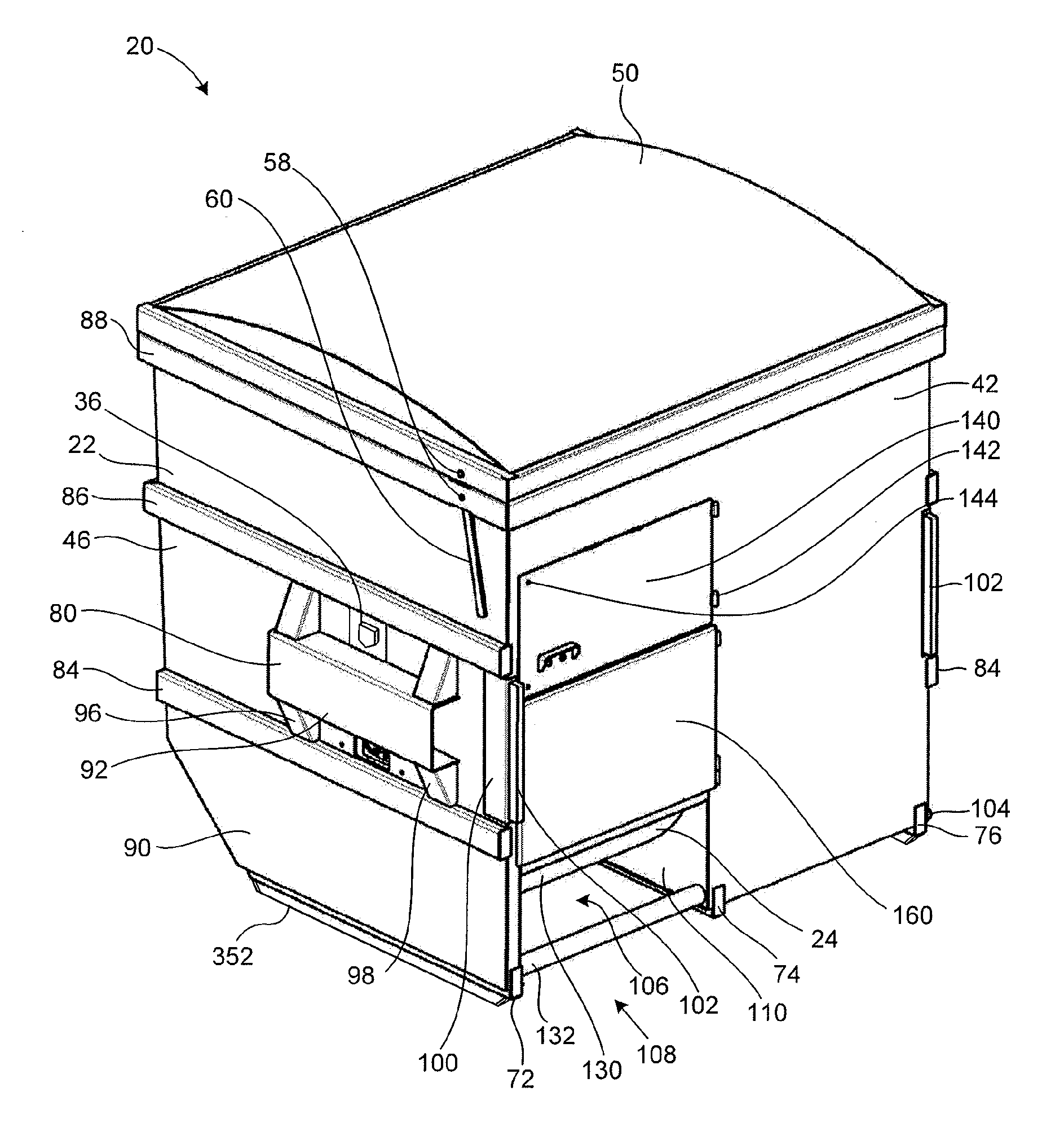
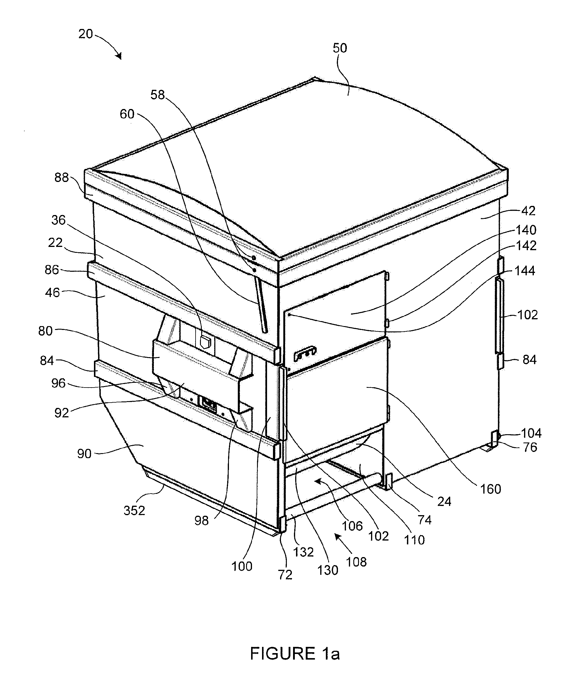
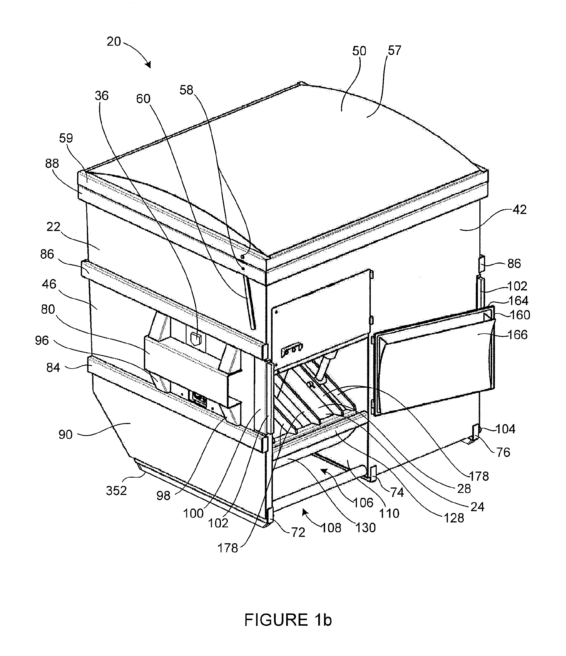
Waste containment apparatus

a technology of waste containment and waste containers, which is applied in the direction of measuring devices, manufacturing tools, instruments, etc., can solve the problems of waste disposal, increased costs of emptying bins, and waste containers that are considered unsightly,

Inactive Publication Date: 2016-01-28
MODERN WASTE PROD
View PDF9 Cites 10 Cited by
  • Summary
  • Abstract
  • Description
  • Claims
  • Application Information

AI Technical Summary

Benefits of technology

The patent describes a containment apparatus that can hold and compact waste or other objects. It has a compaction apparatus that can be moved closer to one side wall of the containment apparatus. The weight sensing assembly is positioned close to the first side wall and can trigger an alarm if the object inside the containment is too heavy. The apparatus also has skids that can hold and move the objectives and can position the weight sensor assembly in different ways. Overall, the patent describes a technical solution for safely and efficiently managing waste.

Problems solved by technology

Waste disposal is often a problem for businesses such as restaurants, gas stations, and convenience stores.
There are many problems or disadvantages with the current method of collection and disposal of waste using a conventional steel bin.
The cost of having the bins emptied has been increasing.
Waste containers may be considered unsightly and are often housed within a surrounding enclosure.
The use of waste compactor devices tends to increase the size of waste collection bins such that they will no longer fit in existing bin enclosures.
Also, it is often difficult to obtain access the back side loading openings of existing compactor devices.
Further, it may be that the fullness of the bin is not known, or unexpectedly heavy material may have been deposited in the bin.
It may not be desirable for a lift-truck to pick up an overweight bin.

Method used


Image

  • Waste containment apparatus
  • Waste containment apparatus
  • Waste containment apparatus

Examples


Embodiment Construction

[0049]The description that follows, and the embodiments described therein, are provided by way of illustration of an example, or examples, of particular embodiments of the principles of the present invention. These examples are provided for the purposes of explanation, and not of limitation, of those principles and of the invention. In the description, like parts are marked throughout the specification and the drawings with the same respective reference numerals. The drawings are not necessarily to scale and in some instances proportions may have been exaggerated, to more clearly to depict certain features of the invention.

[0050]The inventor seeks a fair and reasonable interpretation of the claims, and of this specification. The terminology used in this specification is thought to be consistent with the customary and ordinary meanings of those terms as they would be understood by a person of ordinary skill in the art in North America. Following from the decision of the Court of Appe...


PUM


Abstract

A waste containment apparatus fits within, the same physical envelope as a typical 6 cubic yard bin. The apparatus has lifting fittings to permit conventional lifting and dumping by a garbage truck. The bin has, internally, a compactor including a motor and a compaction head driven by the motor. The working mechanical assemblies and the electrical control unit are mounted well above the inlet chute. The lifting height of the inlet chute is significantly lower than the top opening level of the bin. The unit has an internal refuse flow accumulation path, and internal members such as deflector plates. The unit may have a liquid drain and collection sump. The sump may have a sump heater. The unit has at least one weighing skid that responds to a weight condition in the event that the bin is loaded to an extent that may make it difficult for a lift truck to raise and tip.

Description

FIELD OF INVENTION[0001]This application relates to the field of waste containment apparatus.BACKGROUND OF THE INVENTION[0002]Waste containment and removal is a common activity at many commercial enterprises, such as restaurants, gas stations, apartment buildings, shopping malls and the like. The waste is often collected in large waste containment, a common example being a 6-yard bin i.e., a receptacle that has a nominal capacity of six cubic yards. Waste disposal is often a problem for businesses such as restaurants, gas stations, and convenience stores. There are many problems or disadvantages with the current method of collection and disposal of waste using a conventional steel bin. Typically bins have volumes of about 4, 6 or 8 cubic yards. These bins may tend to be emptied 2 or 3 times per week. The cost of having the bins emptied has been increasing.[0003]Waste generated during the day-to-day operation of the commercial enterprise such as a fast food restaurant, is commonly re...

Claims


Application Information

Patent Timeline
IPC IPC(8): B30B9/30G01G19/52
CPCB30B9/3007G01G19/52B30B9/3046G01G19/4142B30B9/301B30B9/3082
Inventor HANSON, MARKWHITE, BRENT
Owner MODERN WASTE PROD
Learn More