
Vehicle wiper device

a wiper device and wiper technology, applied in vehicle maintenance, vehicle cleaning, domestic applications, etc., can solve the problems of low coupling efficiency, and achieve the effect of reducing coupling efficiency and enlarger the area used

Active Publication Date: 2016-01-28
DENSO CORP
View PDF0 Cites 5 Cited by
  • Summary
  • Abstract
  • Description
  • Claims
  • Application Information

AI Technical Summary

Benefits of technology

The patent aims to improve the coupling between the urging member and the transmission member in a vehicle wiper device. This is achieved by integrating the swing lever and the urging member into a link mechanism, which lowers the coupling efficiency and sometimes requires additional space. The present invention aims to provide a solution that increases coupling efficiency and reduces the size of the device.

Problems solved by technology

This lowers the coupling efficiency.

Method used


Image

  • Vehicle wiper device
  • Vehicle wiper device
  • Vehicle wiper device

Examples


Embodiment Construction

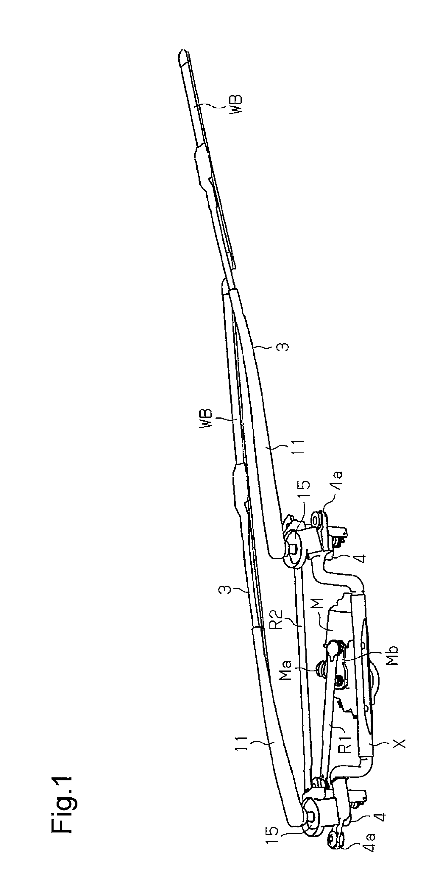
[0027]One embodiment of a vehicle wiper device will now be described with reference to FIGS. 1 to 10.

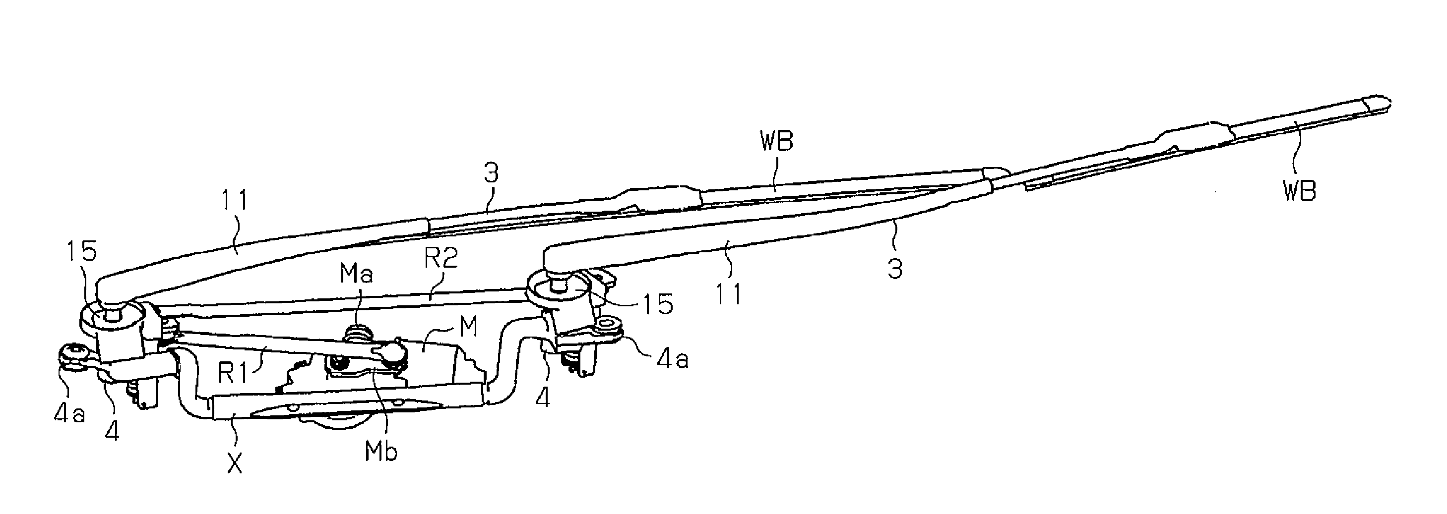
[0028]As shown in FIG. 1, the vehicle wiper device includes two pivot holders 4 (pivot holder at driver seat side, or left side, as viewed in FIG. 1 and pivot holder at passenger seat side, or right side, as viewed in FIG. 1), a hollow frame X, a wiper motor M functioning as a drive source, a drive source link rod R1, and a synchronization link rod R2.

[0029]The wiper motor M, which functions as the drive source, is fixed to an intermediate portion of the hollow frame X. The pivot holders 4 are respectively fixed to two opposite ends of the hollow frame X. In the present embodiment, the pivot holders 4, the hollow frame X, the wiper motor M, and the like form a unit. The unit is supported by a vehicle body at three points when a support portion Ma included in the wiper motor M is fitted to and supported by a fitting hole (not shown) of the vehicle body and a fixing piece 4a included i...


PUM


Abstract

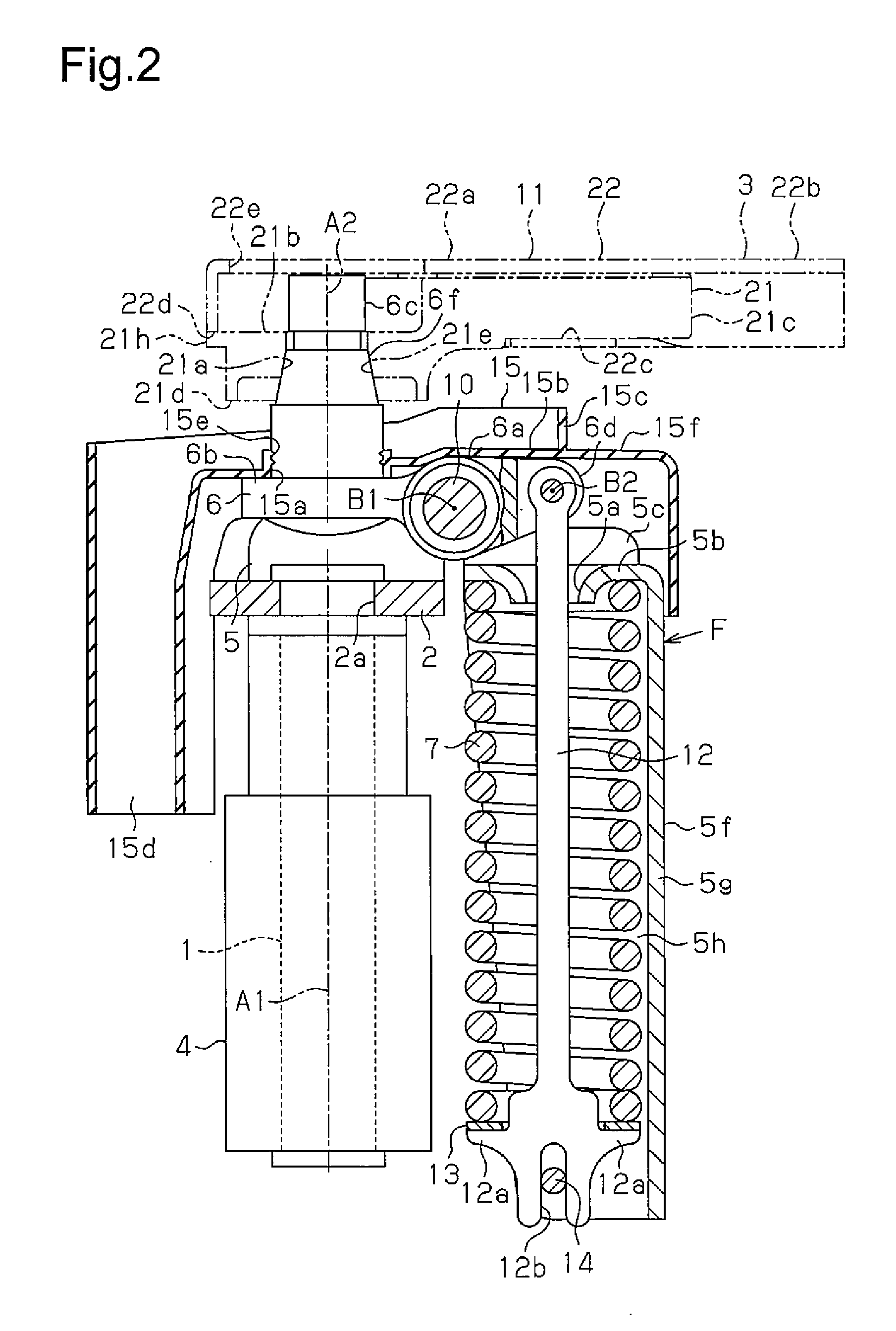
A vehicle wiper device includes a wiper arm, a drive source, a drive shaft that is pivoted by the drive source, and a wiper arm urging member. The wiper arm urging member includes a swing member, an inclination member, a rod, and a compression spring. The inclination member includes a wiper fixing portion and a drawing portion. The rod includes a basal end supported by the drawing portion. A first end of the compression spring is supported by the swing member and the second end applies an urging force to a distal end of the rod. The compression spring acts to draw the drawing portion and urge a distal end of the wiper arm toward a wiped surface.

Description

TECHNICAL FIELD[0001]The present invention relates to a vehicle wiper device.BACKGROUND ART[0002]A conventional vehicle wiper device includes a pivot holder that is fixed to a vehicle body and pivotally supports a pivot shaft. The pivot shaft (drive shaft) includes a basal portion projecting from a lower end of the pivot holder and fixed to a basal portion of a swing lever. The pivot shaft includes a distal portion projecting from an upper end of the pivot holder and coupled to a basal portion (inclination member) of a wiper arm. The swing lever includes a distal portion coupled to a link of a link mechanism, which is driven by a wiper motor. The swing lever swings at a predetermined angle when receiving drive force through the link. When the swing lever swings, the pivot shaft rotates and the wiper arm performs a wiping operation.[0003]Patent document 1 discloses such a vehicle wiper device in which a basal portion (inclination member) of a wiper arm is coupled in a pivotal (inclin...

Claims


Application Information

Patent Timeline
Patent Type & Authority Applications(United States)
IPC IPC(8): B60S1/34B60S1/04
CPCB60S1/3459B60S1/3436B60S1/3465B60S1/0491B60S1/347B60S1/3495B60S1/3468B60S1/3411
Inventor KATO, ATSUSHIHIKIDA, KEIGOBANNO, YOSHIHISA
Owner DENSO CORP
Learn More