Eureka AIR delivers breakthrough ideas for toughest innovation challenges, trusted by R&D personnel around the world.

Optical package having deformable mirrors for focus compensation

a technology of optical packages and mirrors, which is applied in the direction of optical elements, optical radiation measurement, instruments, etc., can solve the problems of significantly reducing the coupling efficiency of the semi-conductor laser with the waveguide, the difficulty of properly aligning the beam, and the insufficient degree of freedom to effectuate the focusing of the beam on the waveguide, so as to facilitate the tip-tilt adjustment of the mirror, the effect of reducing the coupling efficiency of the semi-con

Inactive Publication Date: 2011-03-29
CORNING INC
View PDF10 Cites 0 Cited by
  • Summary
  • Abstract
  • Description
  • Claims
  • Application Information

AI Technical Summary

Benefits of technology

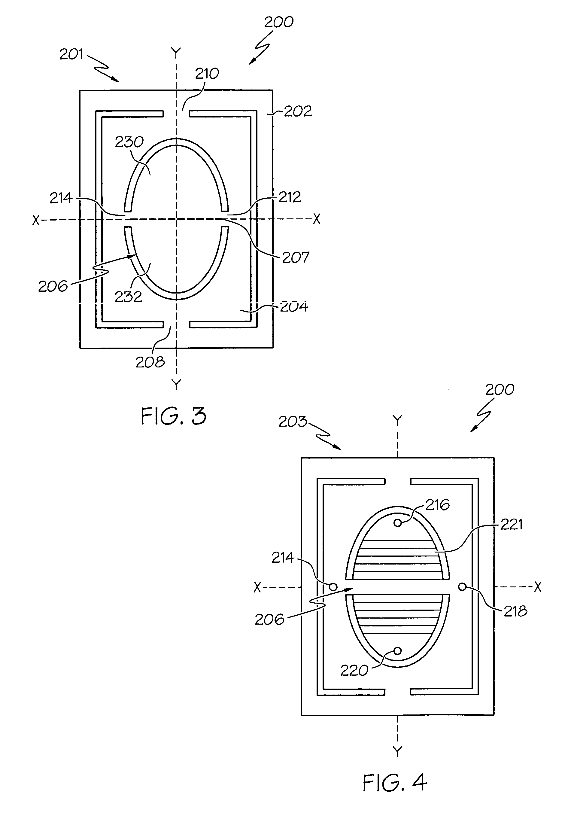
[0004]Waveguide optical mode field diameters of typical SHG crystals, such as MgO-doped periodically poled lithium niobate (PPLN) crystals, can be in the range of a few microns. As a result, the present inventors have recognized that it can be very challenging to properly align the beam from the laser diode with the waveguide of the SHG crystal and maintain the alignment over the lifetime of the optical package and over large operational temperature variations. One possible solution to this problem is to use a mirror system capable of tip / tilt adjustment to perform the lateral alignment of the beam with the waveguide of the SHG crystal. For example, a micro-opto-electromechanical system (MOEMS), micro-electrical mechanical system (MEMS) or similar actuator systems may be operatively coupled to a mirror thereby facilitating tip-tilt adjustment of the mirror. These solutions give excellent results in the lateral dimensions, but do not provide sufficient degrees of freedom to effectuate focusing the beam on the waveguide. While less critical than lateral alignment of the beam with the waveguide, the lack of focus of the beam on the waveguide may significantly decrease the coupling efficiency of the semi-conductor laser with the waveguide. This effect may be more pronounced if the device is exposed to large temperature variations which may further degrade the focus of the beam. Moreover, in lieu of a focus actuator, the precision assembly of the various components in the optical package to a level of a few microns may be required in the axial or focus dimension. Requiring such precision may significantly increase the complexity of the assembly operation and increase the cost of the optical package accordingly.

Problems solved by technology

As a result, the present inventors have recognized that it can be very challenging to properly align the beam from the laser diode with the waveguide of the SHG crystal and maintain the alignment over the lifetime of the optical package and over large operational temperature variations.
These solutions give excellent results in the lateral dimensions, but do not provide sufficient degrees of freedom to effectuate focusing the beam on the waveguide.
While less critical than lateral alignment of the beam with the waveguide, the lack of focus of the beam on the waveguide may significantly decrease the coupling efficiency of the semi-conductor laser with the waveguide.
This effect may be more pronounced if the device is exposed to large temperature variations which may further degrade the focus of the beam.
Requiring such precision may significantly increase the complexity of the assembly operation and increase the cost of the optical package accordingly.

Method used


Image

  • Optical package having deformable mirrors for focus compensation
  • Optical package having deformable mirrors for focus compensation
  • Optical package having deformable mirrors for focus compensation

Examples


Embodiment Construction

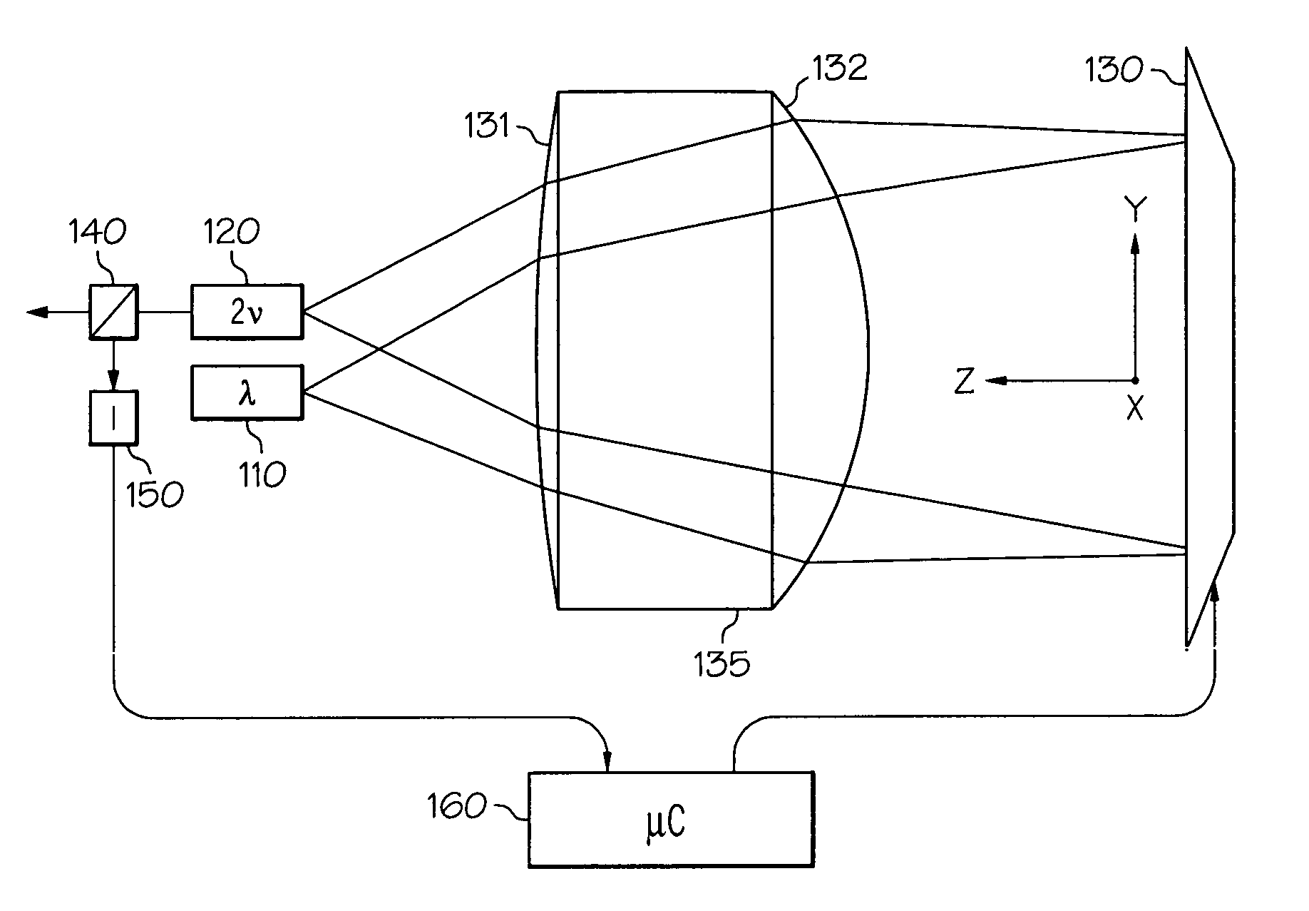
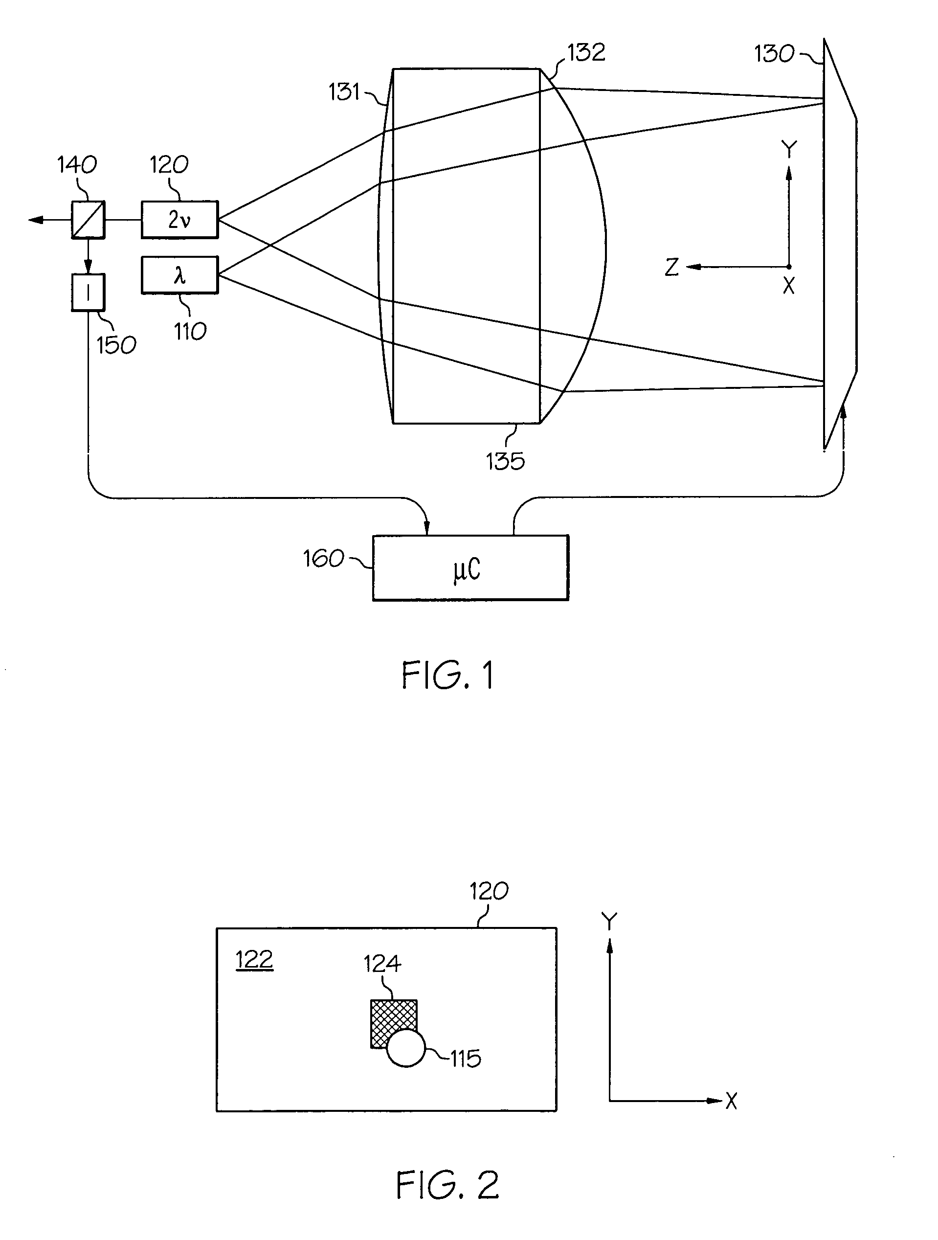
[0021]Referring initially to FIG. 1, although the general structure of the various types of optical packages in which the concepts of particular embodiments of the present invention can be incorporated is taught in readily available technical literature relating to the design and fabrication of frequency or wavelength-converted semiconductor laser sources, the concepts of particular embodiments of the present invention may be conveniently illustrated with general reference to an optical package including, for example, a semiconductor laser 110 (labeled “λ” in FIG. 1) and a wavelength conversion device 120 (labeled “2v” in FIG. 1). In the configuration depicted in FIG. 1, the near infrared light emitted by the semiconductor laser 110 is coupled into a waveguide portion of the wavelength conversion device 120 by one or more adjustable mirrors 130 and a suitable lens assembly 135, which lens assembly 135 may comprise one or more optical elements of unitary or multi-component configurat...


PUM


Abstract

An optical package includes a semiconductor laser, an adjustable mirror and a wavelength conversion device comprising a waveguide portion. The semiconductor laser, adjustable mirror, and wavelength conversion device are oriented to form an optical pathway between an output of the semiconductor laser and an input of the wavelength conversion device. The beam of the semiconductor laser is directed along the optical pathway and onto the adjustable mirror where the beam is reflected by the adjustable mirror onto the waveguide portion of the wavelength conversion device. The adjustable mirror may also be either thermally or mechanically deformable such that, when the adjustable mirror is deformed, the path of the beam along the optical pathway is altered thereby focusing the beam on the waveguide portion of the wavelength conversion device. The adjustable mirror may be adjusted such that the beam of the semiconductor laser is positioned on the waveguide portion of the wavelength conversion device.

Description

CROSS REFERENCE TO RELATED APPLICATIONS[0001]The present application claims priority to U.S. Provisional Patent Application Ser. No. 61 / 049,212, filed on Apr. 30, 2008.BACKGROUND[0002]The present invention generally relates to semiconductor lasers, laser controllers, optical packages, and other optical systems incorporating semiconductor lasers. More specifically, the present invention relates to the use of deformable mirrors for focus compensation in optical packages that include, inter alia, a semiconductor laser and a second harmonic generation (SHG) crystal or another type of wavelength conversion device.BRIEF SUMMARY[0003]Short wavelength light sources can be formed by combining a single-wavelength semiconductor laser, such as an infrared or near-infrared distributed feedback (DFB) laser, distributed Bragg reflector (DBR) laser, or Fabry-Perot laser, with a light wavelength conversion device, such as a second harmonic generation (SHG) crystal. Typically, the SHG crystal is used...

Claims


Application Information

Patent Timeline
Patent Type & Authority Patents(United States)
IPC IPC(8): H01S3/08
CPCG02B26/0825G02B26/0833G02F1/377G02F2001/3503G02F1/3503
Inventor GOLLIER, JACQUESPIECH, GARRETT ANDREW
Owner CORNING INC
Why Eureka
Eureka Blog
Learn More