
Method and machine for knitting tubular knitted articles

a technology for knitting tubular and knitting needles, which is applied in the direction of circular knitting machines, weft knitting, textiles and papermaking, etc., can solve the problems of high production costs, complicated and long-lasting linking processes, and the device for picking up tubular articles is particularly complex and expensive, so as to improve the reliability and reliability of the method, and the machine is more robust and reliable. , the effect of less subject to malfunctions or damages

Active Publication Date: 2016-01-28
STAUBLI ITAL
View PDF10 Cites 8 Cited by
  • Summary
  • Abstract
  • Description
  • Claims
  • Application Information

AI Technical Summary

Benefits of technology

The patent describes a method for making tubular knitted articles by joining the opposite edge portions with sewing or linking, instead of sewing them directly. The method also includes steps for blocking the stitches before removing them and using mechanical members to engage the stitches with the pick-up hooks. The method allows for easier handling of the finished article and a more robust machine design. The method also includes a step for lifting or raising the article from a loop formation plane to make it easier for the pick-up hooks to pick it up. Overall, the patent provides a simplified and reliable process for making tubular knitted articles.

Problems solved by technology

This traditional method is labor-consuming and therefore involves high production costs.
The article thus obtained has high quality but the linking process is complex and long-lasting; furthermore the device for pick the tubular article up is particularly complex and expensive.
A very coarse and low-quality article of manufacture is obtained with this known device, which in addition generates a large amount of scraps.
Scraps are undesired, since they increase the overall manufacturing costs and generate waste which must be disposed of.
All these systems have inconveniences due to the complexity of the devices for handling the tubular knitted article or due to a low reliability.

Method used


Image

  • Method and machine for knitting tubular knitted articles
  • Method and machine for knitting tubular knitted articles
  • Method and machine for knitting tubular knitted articles

Examples


Embodiment Construction

[0110]The following detailed description of the exemplary embodiments refers to the accompanying drawings. The same reference numbers in different drawings identify the same or similar elements. Additionally, the drawings are not necessarily drawn to scale. Also, the following detailed description does not limit the invention. Instead, the scope of the invention is defined by the appended claims.

[0111]Reference throughout the specification to “one embodiment” or “an embodiment” or “some embodiments” means that the particular feature, structure or characteristic described in connection with an embodiment is included in at least one embodiment of the subject matter disclosed. Thus, the appearance of the phrase “in one embodiment” or “in an embodiment” or “in some embodiments” in various places throughout the specification is not necessarily referring to the same embodiment(s). Further, the particular features, structures or characteristics may be combined in any suitable manner in one...


PUM


Abstract

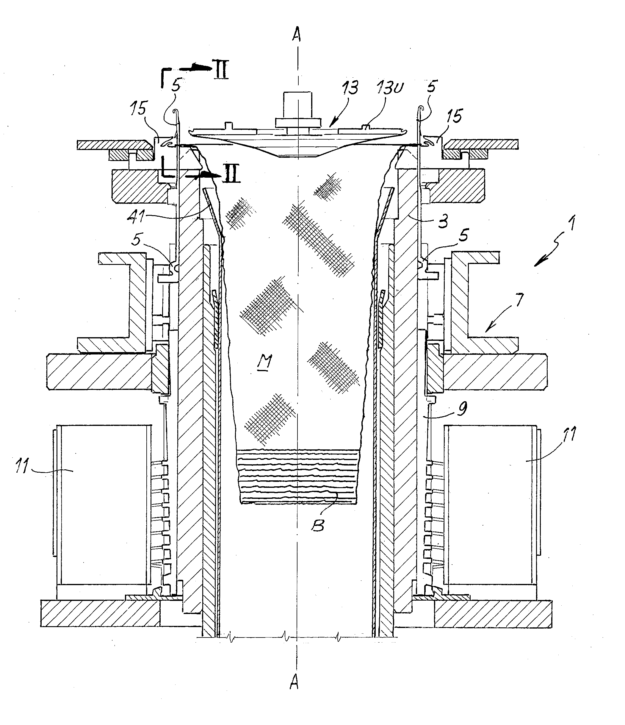
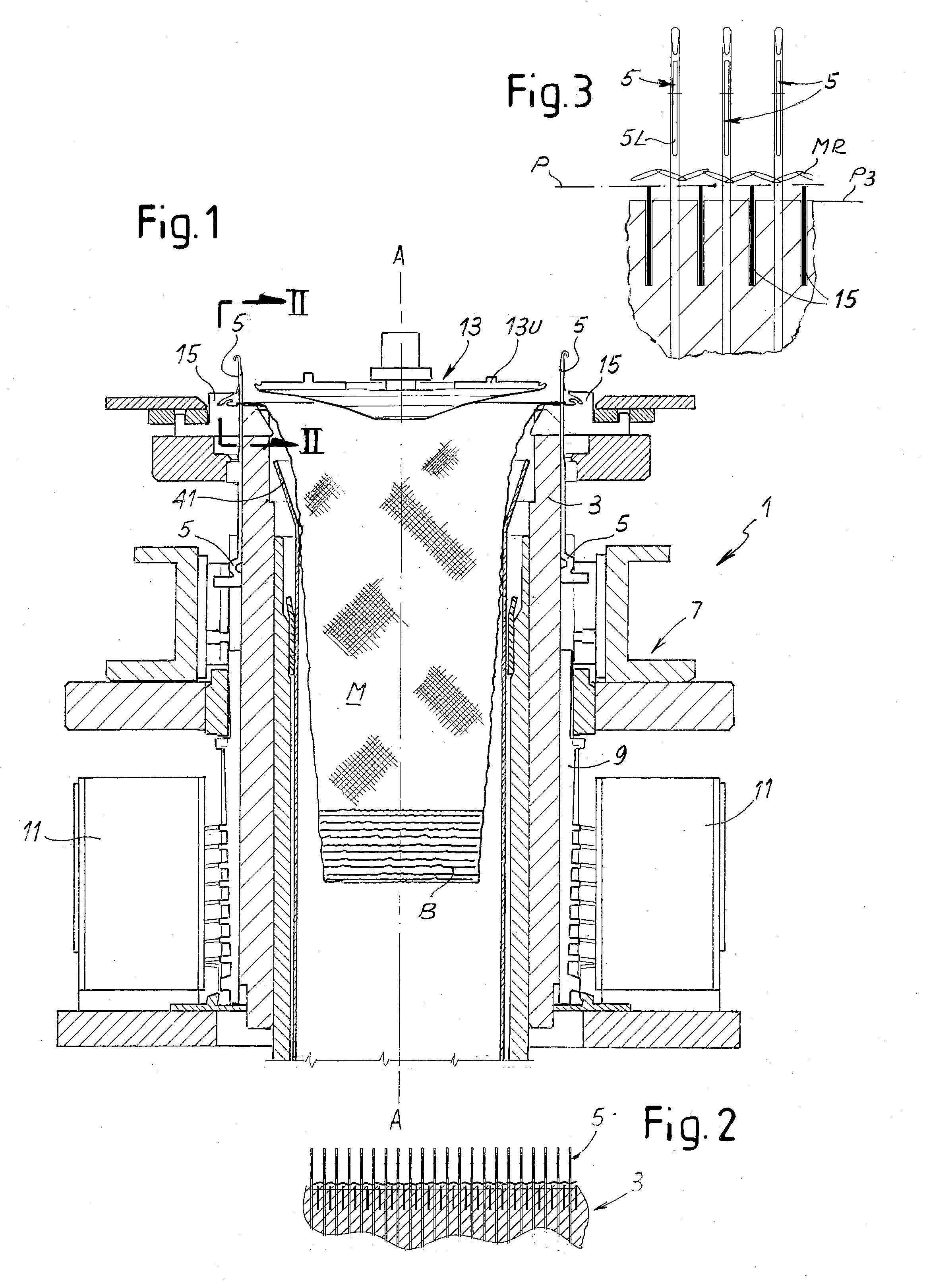
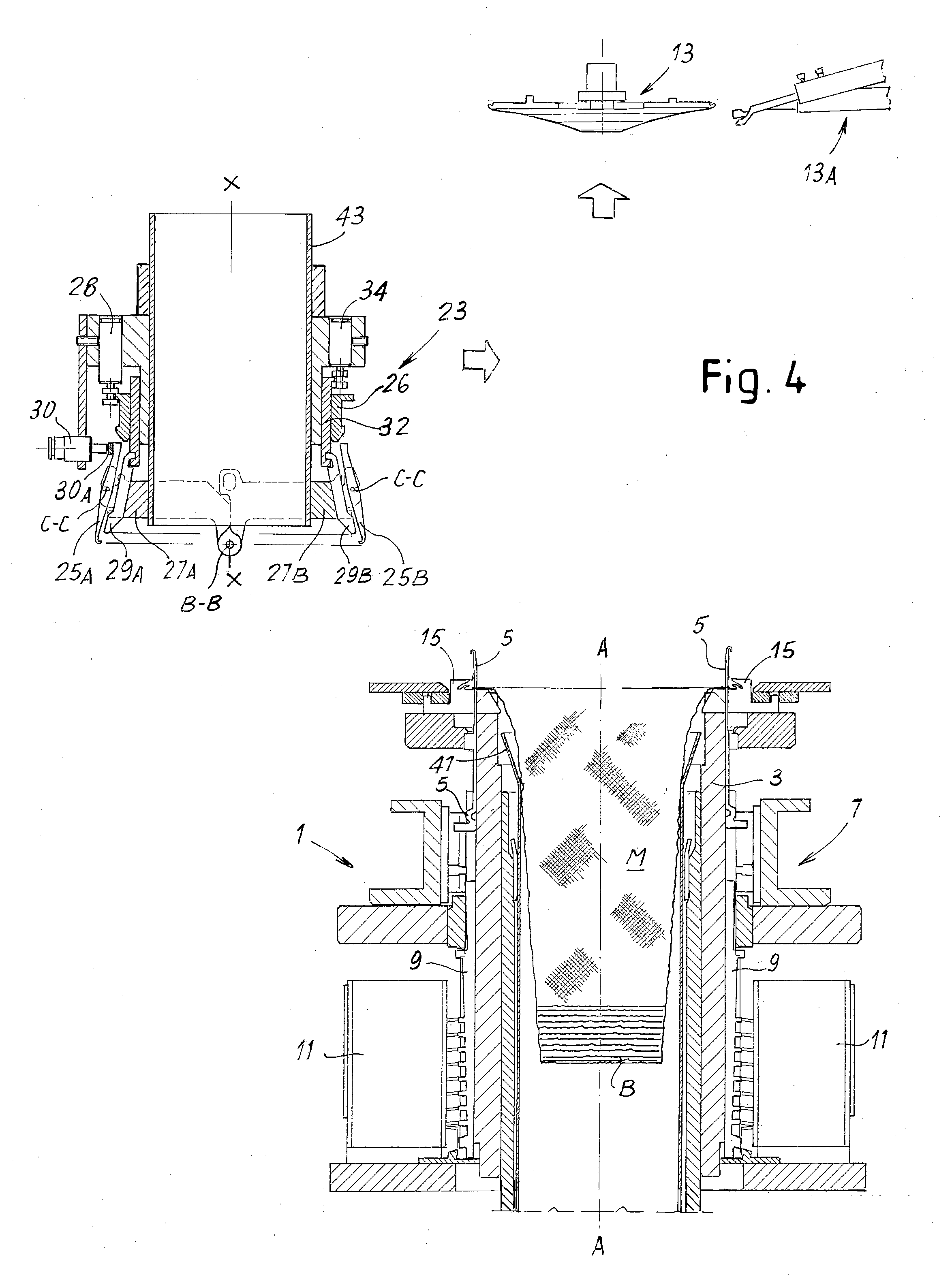
The method provides for arranging a pick-up member for the tubular knitted article (M) coaxially with the needle cylinder, when knitting has been completed. The pick-up member (23) is provided with a plurality of pick-up hooks (25A, 25B) arranged according to a circular ring subdivided into two circular half-rings that can be overturned over each other. The tubular article is engaged by the pick-up hooks while the stitches of the last course of the knitted article are still held by the needles (5) of the knitting machine. The stitches of the last curse are then removed from the needles and the tubular article is removed from the needle cylinder (3) by means of the pick-up member (23). The two half-rings of pick-up hooks are overturned one onto the other, putting one of two opposite edges of the toe of the tubular article onto the other. The two edges are then sewn or linked.

Description

TECHNICAL FIELD[0001]The present invention relates to methods and machines for producing tubular knitted articles, such as socks and stockings.STATE OF THE ART[0002]For producing tubular articles, especially socks, circular knitting machines are used; these machines knit the article starting from an elastic border or edge up to an opposite end defining edge portions that, once sewn together, form the toe of the sock. In traditional machines, once the article has been knitted, the article is unloaded with the open toe, and the articles coming from one or more circular knitting machines are transferred to a sewing or linking machine or device. An operator picks up single articles, holding them at the toe end, and introduces them into the sewing machine or the linking machine to close the end of the toe. This traditional method is labor-consuming and therefore involves high production costs.[0003]Devices and circular knitting machines have been studied to automatically pick up the tubu...

Claims


Application Information

Patent Timeline
Patent Type & Authority Applications(United States)
IPC IPC(8): D04B9/40D04B9/44D04B15/02
CPCD04B9/40D04B9/44D04B15/02D04B1/108D04B15/92
Inventor CONTIVENNI, MASSIMO
Owner STAUBLI ITAL
Learn More