Fitting and flat bar for textile processing machine

A technology of processing machine and cover bar, which is applied in the direction of textile and paper making, deburring device, fiber treatment, etc. It can solve the problems of expensive card clothing structure, expensive regrinding times, limited and other problems, and achieves easy assembly and disassembly, high fatigue The effect of intensity

Active Publication Date: 2014-10-15
TRUETZSCHLER GRP SE
View PDF8 Cites 5 Cited by
  • Summary
  • Abstract
  • Description
  • Claims
  • Application Information

AI Technical Summary

Problems solved by technology

Disadvantage is the complex construction of the clothing, in which the clothing strips are first glued to the slats in order to then be fixed magnetically in the recesses of

Method used


Image

  • Fitting and flat bar for textile processing machine
  • Fitting and flat bar for textile processing machine
  • Fitting and flat bar for textile processing machine

Examples


Embodiment Construction

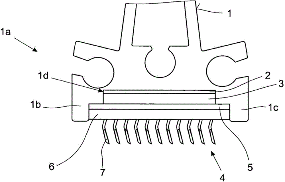
[0029] exist figure 1 A known flat rod 1 according to the prior art is shown in a side view. The flat bar 1 includes a flat head, not shown here, which, due to its geometry, is rigid enough to pass over the width of the cylinder of a carding machine (Karde) or carding machine (Krempel). Its zigzag wires create a constant carding gap. On the flat foot 1a, the two webs 1b, 1c arranged on both sides form a recess 1d which is suitable for receiving at least one flat clothing 4 . According to the example, this recess 1 d is embodied in two stages, so that the magnet 3 is firmly connected to the cover rod 1 via the fastening 2 . The fastening 2 can be embodied as an adhesive connection or another materially bonded connection, or also as a mechanical connection. The flat clothing 4 essentially comprises a carrier element 6 for receiving the small hooks 7 and a steel plate 5 which is connected to the carrier element 6 . The carrier element 6 usually consists of a textile or fabric...


PUM


Abstract

The invention relates to a fitting strip for use in a textile processing machine, comprising a plurality of tooth segments (10), each of which comprises multiple teeth (13), each tooth having a tooth head (11) and a tooth base (12). The tooth segments (10) are arranged parallel to one another and are directly or indirectly connected to one another. The fitting strip is characterized in that the tooth segments (10) are connected in a bonded manner. The flat bar according to the invention is characterized in that the fitting strip (8) comprises a plurality of tooth segments (10) which can be fixed to the flat bar by means of a magnetic force.

Description

technical field [0001] The invention relates to a card clothing and a flat bar for a textile processing machine. Background technique [0002] Cards have, among other tasks, the task of opening fiber tufts into individual fibers and opening neps. For this purpose, the fiber bundles are guided between the cylinder and the revolving flat, wherein the fibers are oriented and separated. For this purpose, the cylinder is usually provided with a circumferential zigzag wire, in which the individual teeth are produced from a flat wire by means of punching. The revolving flats usually consist of a number of flat bars with flexible clothings, in which a number of individual wires are fixed in an elastic fabric lining, the tips of which meet at very narrow distances from the tips of the zigzag wires of the cylinder. Fit and thus form a carding gap. [0003] In order to reliably ensure a narrow carding gap during the long-term operation of the card, all relevant components must have ...

Claims


Application Information

Patent Timeline
IPC IPC(8): D01G15/88D01G15/24
CPCD01G15/88D01G15/24
Inventor 阿米尼·莱德
Owner TRUETZSCHLER GRP SE
Why Eureka
Try Eureka