Cylindrical valve assembly

a cylindrical valve and assembly technology, applied in the direction of machine/engine, manufacturing tools, and sanders, etc., can solve the problems of undetected interruption of internal airflow, change in internal geometry and volume of the valve assembly, and inability to meet the needs of the customer, so as to achieve constant internal geometry and effect of

Active Publication Date: 2016-01-28
POSTEVKA VALENTIN
View PDF20 Cites 5 Cited by
  • Summary
  • Abstract
  • Description
  • Claims
  • Application Information

AI Technical Summary

Benefits of technology

[0004]In various exemplary embodiments, the present disclosure provides an improved cylindrical valve assembly that maintains a substantially constant internal geometry a

Problems solved by technology

These valves all suffer from a common shortcoming—when the shutter mechanism is actuated, the internal geometry and volume of the valve assembly is changed and the internal intake flow through the valv

Method used


Image

  • Cylindrical valve assembly
  • Cylindrical valve assembly
  • Cylindrical valve assembly

Examples


Embodiment Construction

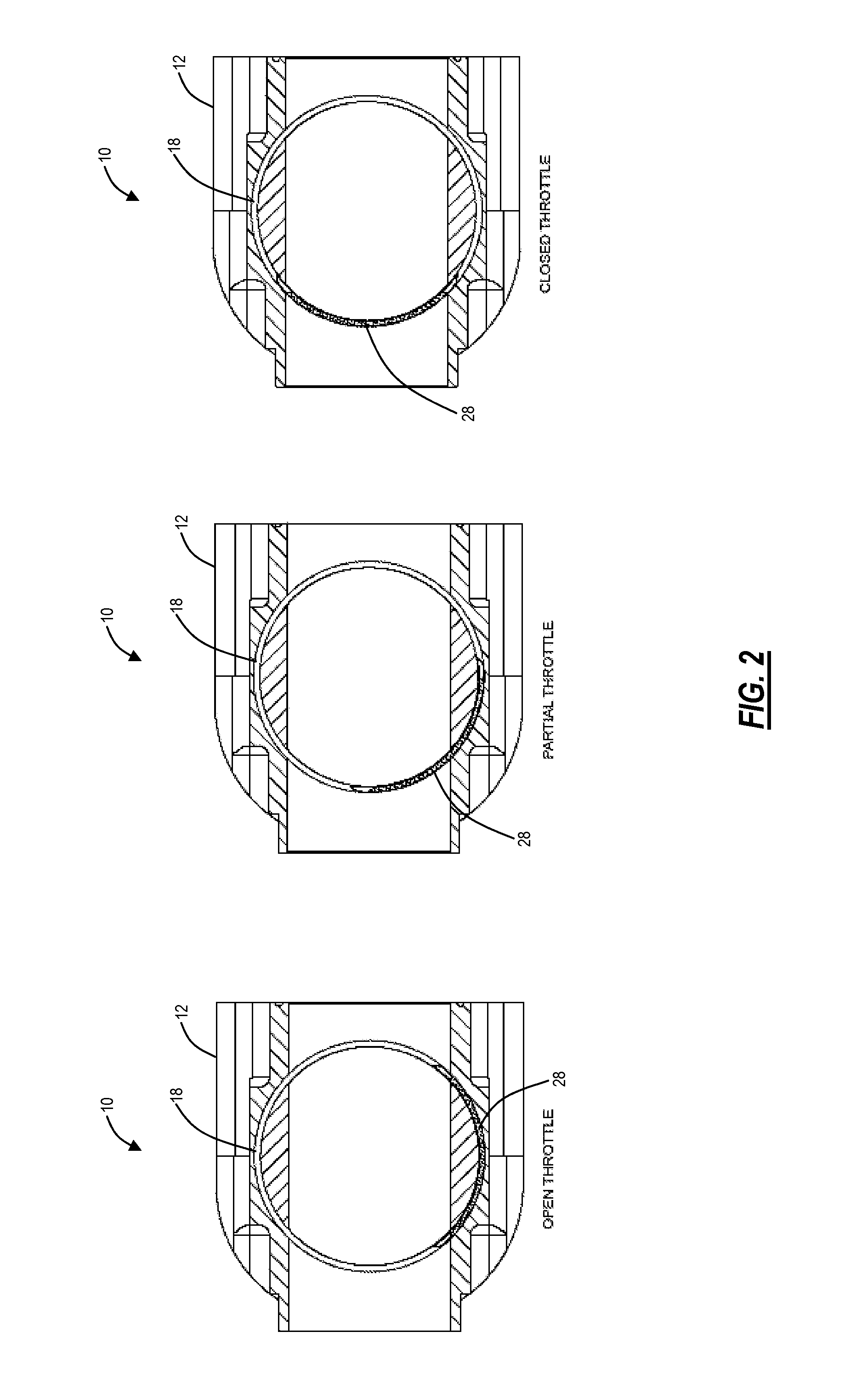
[0022]Again, in various exemplary embodiments, the present disclosure provides an improved cylindrical valve assembly that maintains a substantially constant internal geometry and volume upon actuation, when the shutter mechanism / valve door is opened or closed, such that the internal intake flow is substantially constant and uninterrupted.

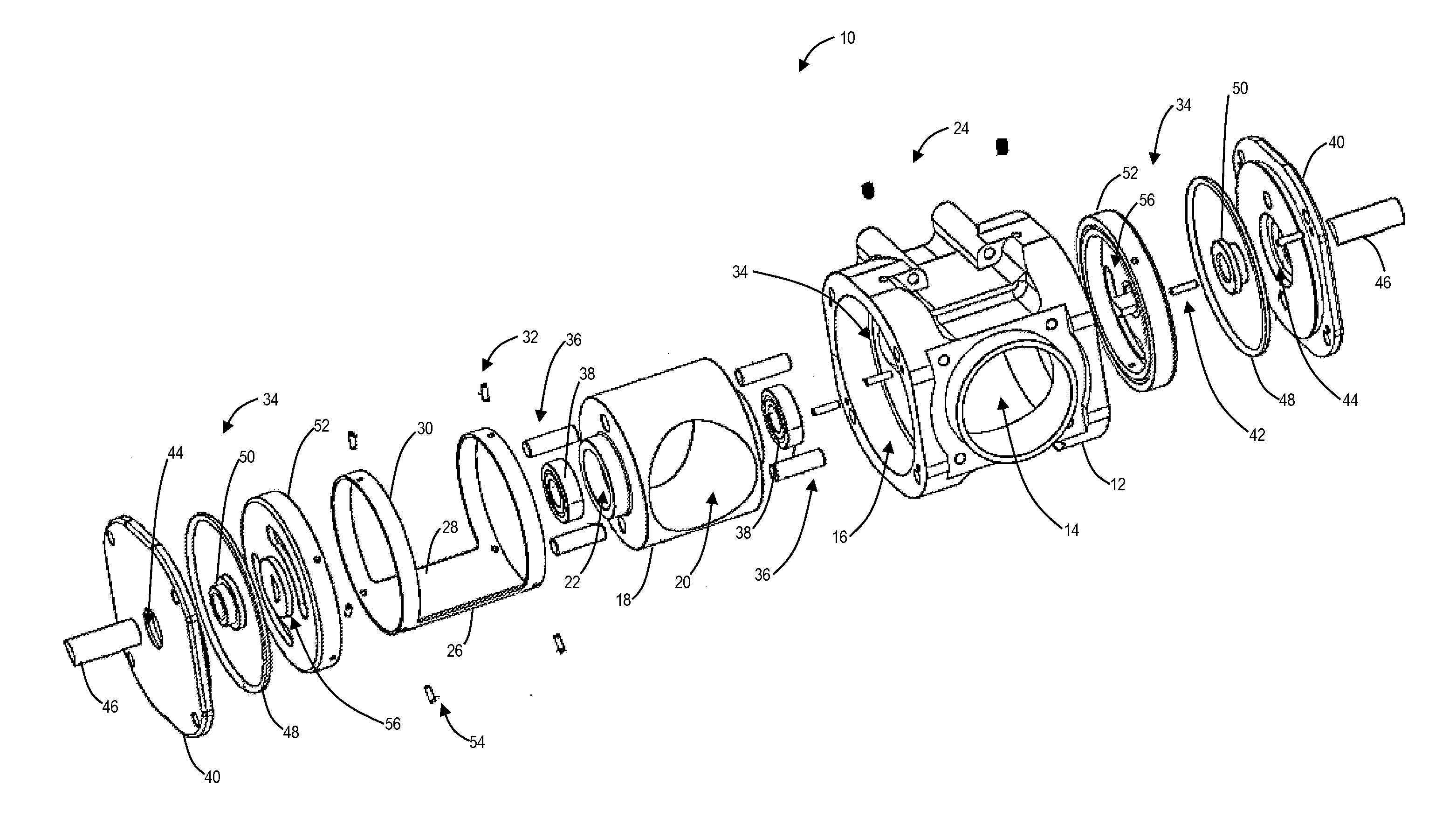
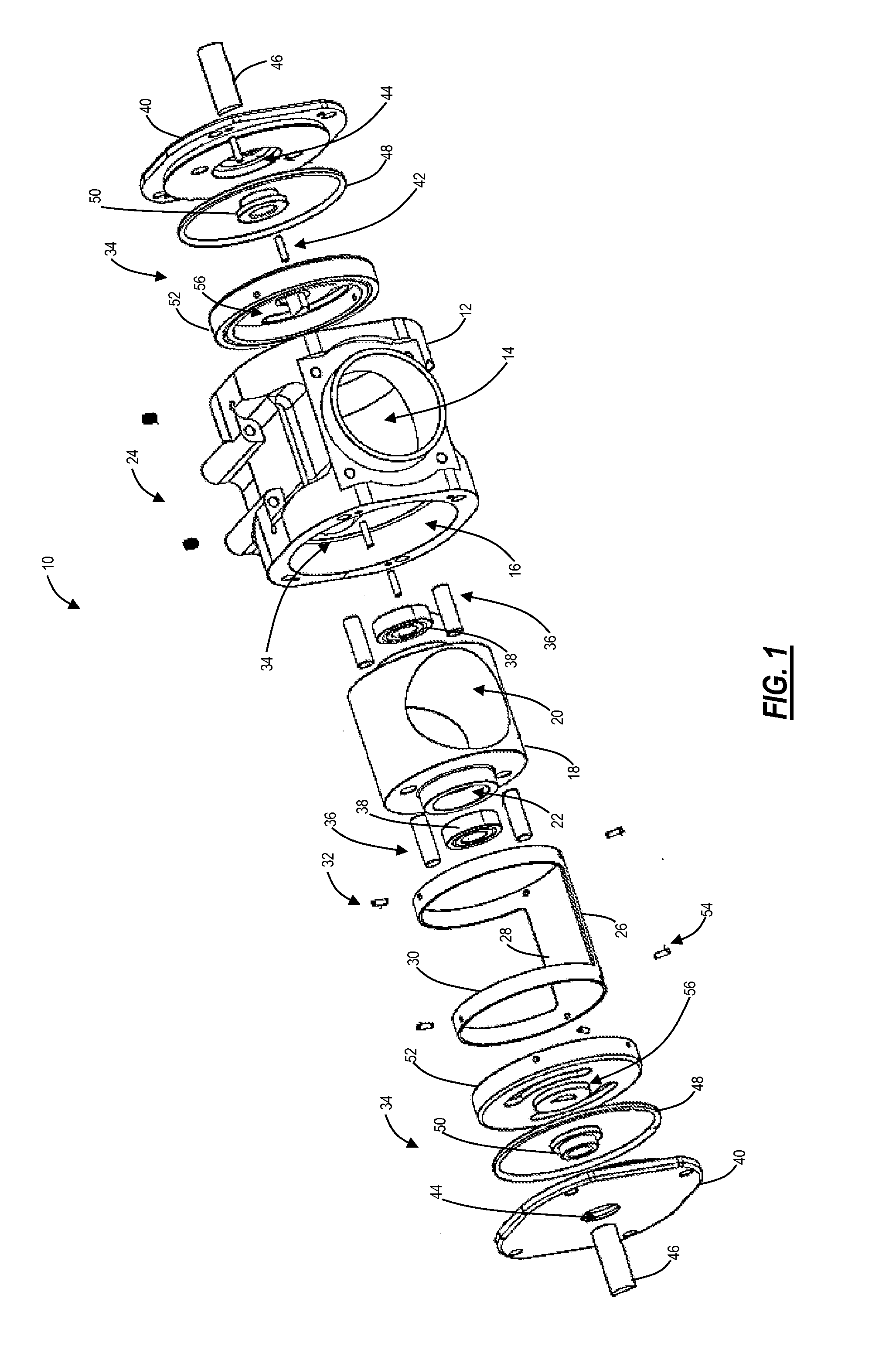
[0023]Referring now specifically to FIG. 1, in one exemplary embodiment, the cylindrical valve assembly 10 includes a housing 12. The housing 12 includes a substantially cylindrical interior portion and an exterior portion that includes any desired structures for attaching the housing 12 to an external system, such as an engine or the like. The housing 12 includes a pair of first ports 14 for receiving and delivering the intake flow and a pair of second ports 16 for receiving the other components of the cylindrical valve assembly 10. A cylindrical core 18 is fixedly disposed within the housing 12. The cylindrical core 18 includes a pair of third po...


PUM

PropertyMeasurementUnit
Structureaaaaaaaaaa
Volumeaaaaaaaaaa
Velocityaaaaaaaaaa

Abstract

A cylindrical valve assembly, including: a housing defining a port, an interior volume, and an interior surface; a lip structure disposed about the periphery of the port, wherein the lip structure protrudes into the interior volume past the interior surface of the housing; and a valve door defining an exterior surface disposed concentrically within the housing, wherein the valve door is configured to move from an open configuration in which it does not obstruct the port to a closed configuration in which it does obstruct the port, and wherein, when the valve door is in the closed configuration, the exterior surface of the valve door is in contact with the lip structure and not the interior surface of the housing. Optionally, the lip structure is provided by an insert structure that is disposed through the port. Optionally, an end of the insert structure opposite the lip structure includes a velocity stack. Optionally, a plurality of dimples are manufactured into the exterior surface of the valve door.

Description

CROSS-REFERENCE TO RELATED APPLICATION[0001]The present disclosure is a continuation-in-part (CIP) of co-pending U.S. patent application Ser. No. 14 / 331,733, filed on Jul. 15, 2014, and entitled “CYLINDRICAL VALVE ASSEMBLY,” which claims the benefit of priority of U.S. Provisional Patent Application No. 61 / 847,595, filed on Jul. 18, 2013, and entitled “CYLINDRICAL VALVE ASSEMBLY,” the contents of both of which are incorporated in full by reference herein.FIELD OF THE DISCLOSURE[0002]The present disclosure relates generally to an improved cylindrical valve assembly. More specifically, the present disclosure relates to an improved cylindrical valve assembly that provides a substantially constant internal geometry and volume upon actuation, such that the internal intake flow is substantially constant and uninterrupted. The improved cylindrical valve assembly of the present disclosure (also variously referred to as a rotary valve, a roller valve, a barrel valve, a butterfly valve, or a ...

Claims


Application Information

Patent Timeline
IPC IPC(8): F16K5/04B23P15/00
CPCF16K5/04B23P15/001F16K5/0421F16K13/02F02D9/16
Inventor POSTEVKA, VALENTIN
Owner POSTEVKA VALENTIN
Why Eureka
Try Eureka