Mobile communication system and user terminal

a mobile communication system and user terminal technology, applied in the field of mobile communication systems, can solve problems such as no mechanism for appropriately controlling dual connectivity

Active Publication Date: 2016-01-28
KYOCERA CORP
View PDF2 Cites 44 Cited by
  • Summary
  • Abstract
  • Description
  • Claims
  • Application Information

AI Technical Summary

Problems solved by technology

However, in the current situation, there is a problem that ther...

Method used


Image

  • Mobile communication system and user terminal
  • Mobile communication system and user terminal
  • Mobile communication system and user terminal

Examples


first embodiment

[0058]Hereinafter, with reference to the accompanying drawings, an embodiment will be described in a case where the present disclosure is applied to LTE (Long Term Evolution) standardized by 3GPP.

[0059](Configuration of LTE System)

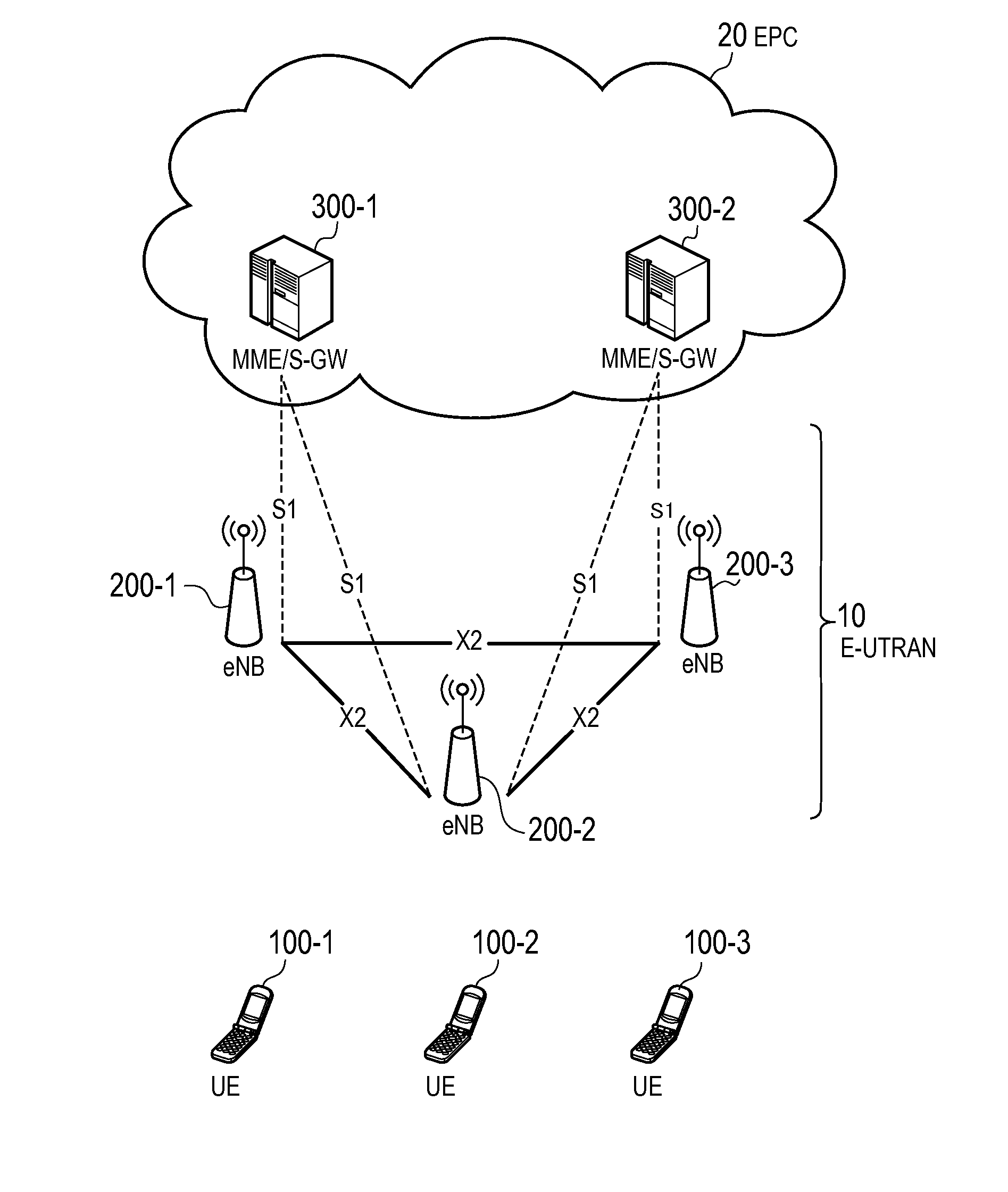
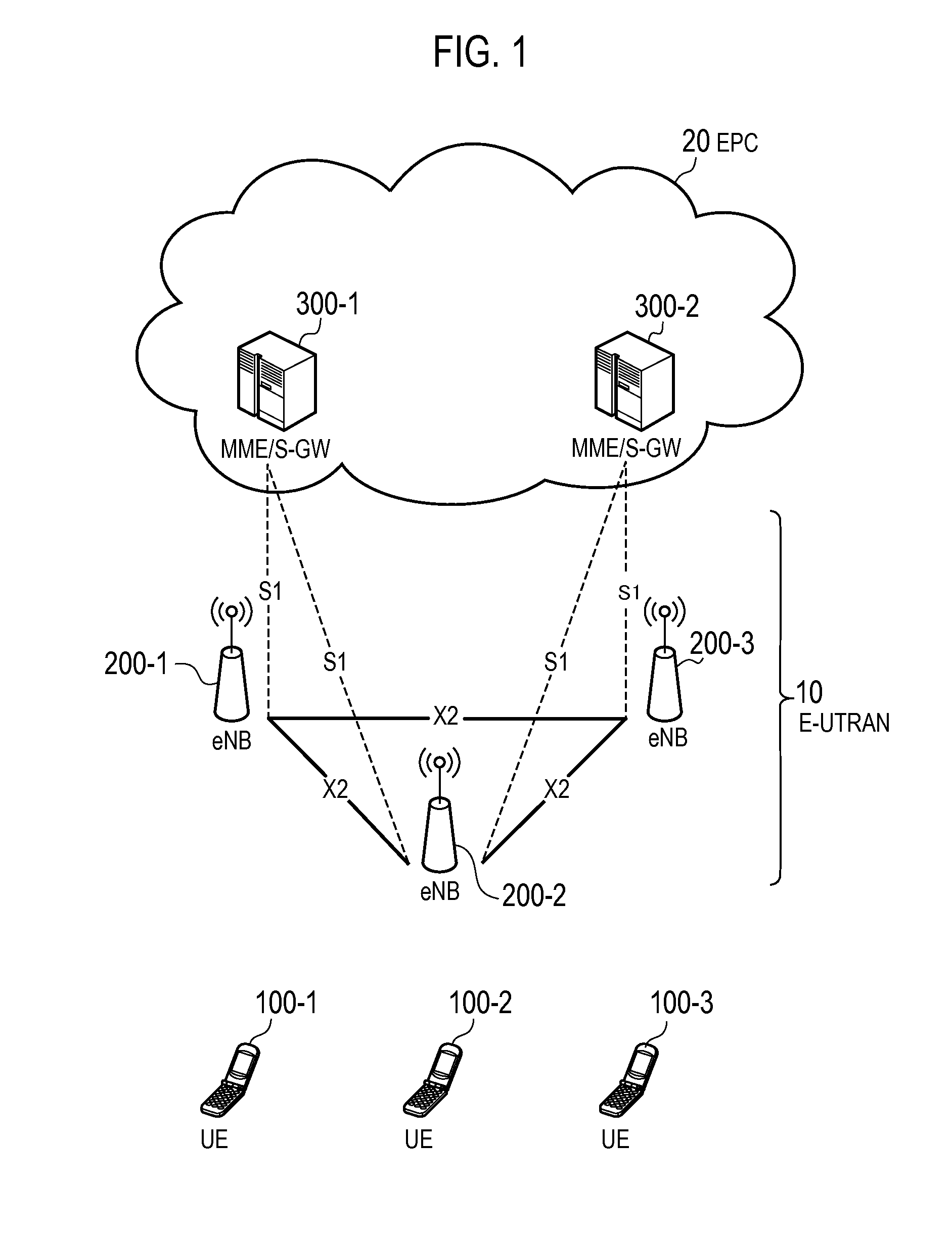
[0060]FIG. 1 is a configuration diagram of an LTE system according to a first embodiment. As illustrated in FIG. 1, the LTE system includes a plurality of UEs (User Equipments) 100, E-UTRAN (Evolved-UMTS Terrestrial Radio Access Network) 10, and EPC (Evolved Packet Core) 20. The E-UTRAN 10 corresponds to a radio access network and the EPC 20 corresponds to a core network. The E-UTRAN 10 and the EPC 20 constitute a network of the LTE system.

[0061]The UE 100 is a mobile communication device and performs radio communication with a cell (a serving cell) with which a connection is established. The UE 100 corresponds to the user terminal.

[0062]The E-UTRAN 10 includes a plurality of eNBs 200 (evolved Node-Bs). The eNB 200 corresponds to the base station. The eNB ...

second embodiment

[0174]The second embodiment will be described while focusing on the differences from the first embodiment.

[0175]Although the operation of the UE 100 in the connected state is described in the first embodiment, an operation of the UE 100 in an idle state will be described in the second embodiment. It is noted that an operation environment of the second embodiment is similar to that of the first embodiment (see FIG. 6).

[0176]When the UE 100 that supports a dual connectivity is in an idle state and is camping in the small cell, first of all, the UE 100 establishes connection with the small cell, and thus, the control of the dual connectivity becomes complicated. “Camping in the small cell” means selecting the small cell as a serving cell in the idle state. Thus, in the second embodiment, the UE 100 that supports a dual connectivity is controlled to camp in the large cell.

[0177](a) Operation Pattern 1

[0178]In an operation pattern 1 according to the second embodiment, the eNB 200-2 that ...


PUM


Abstract

A base station is used for a mobile communication system that supports a dual connectivity. The base station includes a controller configured to establish an RRC connection with a user terminal, and to perform a mobility control in the dual connectivity.

Description

CROSS REFERENCE[0001]The entire contents of U.S. Provisional Application No. 61 / 808,794 (filed on Apr. 5, 2013), U.S. Provisional Application No. 61 / 864,186 (filed on Aug. 9, 2013), and U.S. Provisional Application No. 61 / 934,241 (filed on Jan. 31, 2014) are incorporated herein by reference.TECHNICAL FIELD[0002]The present disclosure relates to a mobile communication system that supports a dual connectivity.BACKGROUND ART[0003]In 3GPP (3rd Generation Partnership Project) which is a project aiming to standardize a mobile communication system, introduction of a dual connectivity has been discussed (see Non-patent document 1).[0004]The dual connectivity is a scheme in which a user terminal establishes a pair of connections with a pair of cells which is a combination of cells managed by different base stations.PRIOR ART DOCUMENTNon-Patent Document[0005]Non-patent document 1: 3GPP Contribution RP-122033SUMMARY[0006]However, in the current situation, there is a problem that there is no me...

Claims


Application Information

Patent Timeline
IPC IPC(8): H04W72/04H04B7/06H04W8/24H04W74/00
CPCH04W72/0426H04W74/002H04W88/10H04W8/24H04B7/0632H04B7/022H04W76/15H04W76/27H04W72/27H04W74/0833H04W88/02
Inventor FUKUTA, NORIYOSHIMORITA, KUGOYAMAZAKI, CHIHARUCHANG, HENRYKALHAN, AMITNAGASAKA, YUSHIFUJISHIRO, MASATOKASHIWASE, SUSUMU
Owner KYOCERA CORP
Why Eureka
Try Eureka