Cystoscopic device and methods for operating same

a technology of cystoscope and cystoscope, which is applied in the field of cystoscope procedures, can solve the problems of prolonged bleeding, prolonged operation time, and temporary loss of visual orientation

Inactive Publication Date: 2016-02-04
KUMAR ANIL
View PDF1 Cites 4 Cited by
  • Summary
  • Abstract
  • Description
  • Claims
  • Application Information

AI Technical Summary

Problems solved by technology

These periodic interruptions produce dangerous difficulties such as temporary loss of visual orientation, prolonged bleeding and extended operative time.
Thus, a conventional cystoscope does not permit a simultaneous procedure and observation.

Method used


Image

  • Cystoscopic device and methods for operating same
  • Cystoscopic device and methods for operating same

Examples


Embodiment Construction

[0016]As is known to the skilled artisan, endoscopic instruments are widely used in urology and are introduced through the urethra to perform various medical procedures at the operative field such as the bladder, prostate or urethra. Typical instruments being the resectoscope, urethro-cystoscope, lithotriptor, and biopsy endoscopic forceps. For ease of description and illustration, the specification herein will disclose and describe the invention in specific connection with a cystoscope and, therefore, should not be limited thereby.

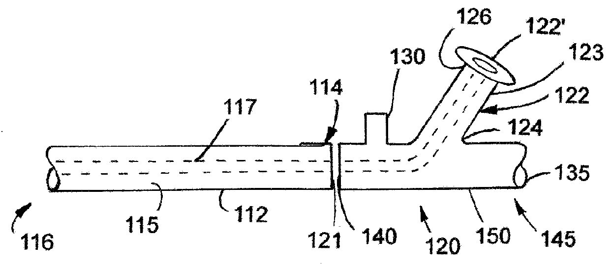
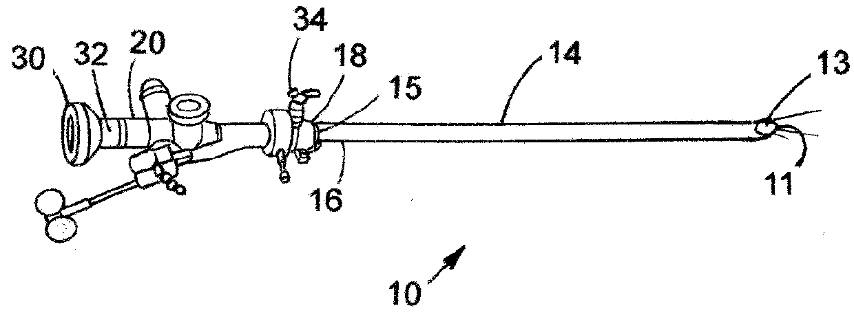
[0017]Referring now to the drawing and, in particular, FIG. 1 there is depicted a conventional cystoscope 10. The cystoscope 10 includes a tubular sheath 14 which provides a passageway through the human urethra to the area of visual and operative interest. The sheath 14 includes a hollow inserting portion 12 at its distal end 13 and a proximal main body 16. The distal end 13 of the inserting portion 12 has a distal opening 11. At its proximal end 15 the s...


PUM


Abstract

A cystoscope device and method for operating and using same are disclosed. The cystoscope comprises a sheath and a bridge removably connected thereto. The bridge includes an offset lens assembly including an upper eyepiece; a light source, and a fiber optic connected to a light source. The lens or eyepiece enables observation within a urological organ while contemporaneously conducting a urological procedure.

Description

CROSS-REFERENCE TO RELATED APPLICATION[0001]This application is a completion application of co-pending U.S. Provisional Patent Application Ser. No. 62 / 030,934, filed Jul. 30, 2014 for “Cystoscopic Device and Methods for Operating Same”, the entire disclosure of which is hereby incorporated by reference, including the drawing.BACKGROUND OF THE INVENTION[0002]1. Field of the Invention[0003]This present invention relates to cystoscopy procedures and, more particularly, to cystoscope devices and methods for operating same.[0004]2. Prior Art[0005]Known cystoscopes are typically used for diagnostic and surgical medical procedures such as a cystoscopy. Cystoscopes are used to examine the urinary bladder and the interior urethra wall. Typically, cystoscopes have a flexible insertion tube that is inserted into a patient during a cystoscopy procedure. During insertion, the position of the distal end of the insertion tube is controlled by control devices on the cystoscope's handle at the proxi...

Claims


Application Information

Patent Timeline
Patent Type & Authority Applications(United States)
IPC IPC(8): A61B1/00A61B1/12A61B1/07A61B1/307
CPCA61B1/12A61B1/00195A61B1/07A61B1/307A61B1/015
Inventor KUMAR, ANIL
Owner KUMAR ANIL
Why Eureka
Try Eureka