Fingerprint recognition method and device thereof

Active Publication Date: 2016-02-04
EGIS TECH
View PDF3 Cites 10 Cited by
  • Summary
  • Abstract
  • Description
  • Claims
  • Application Information

AI Technical Summary

Benefits of technology

[0010]According to the objective of the present invention, a fingerprint recognition device is further provided, which may comprise: a fingerprint sensor; a control processor electrically coupled to the fingerprint sensor, and a storage electrically coupled the control processor, wherein, the control processor may be used to execute the following steps: (a) obtaining a to-be-recognized fingerprint image of a to-be-recognized finger; (b) extracting to-be-recognized data of the to-be-recognized fingerprint image, the to-be-recognized data including a to-be-recognized minutiae

Problems solved by technology

Nonetheless, it is still subject to the issue of lower reliability in terms of smaller area fingerprint verification which obtains fingerprint information using a fingerprint sensor with a smaller sensing area.
However, the original fingerprint images have to be stored, and therefore, larger storage space is needed.
Also, the r

Method used


Image

  • Fingerprint recognition method and device thereof
  • Fingerprint recognition method and device thereof
  • Fingerprint recognition method and device thereof

Examples


example 1

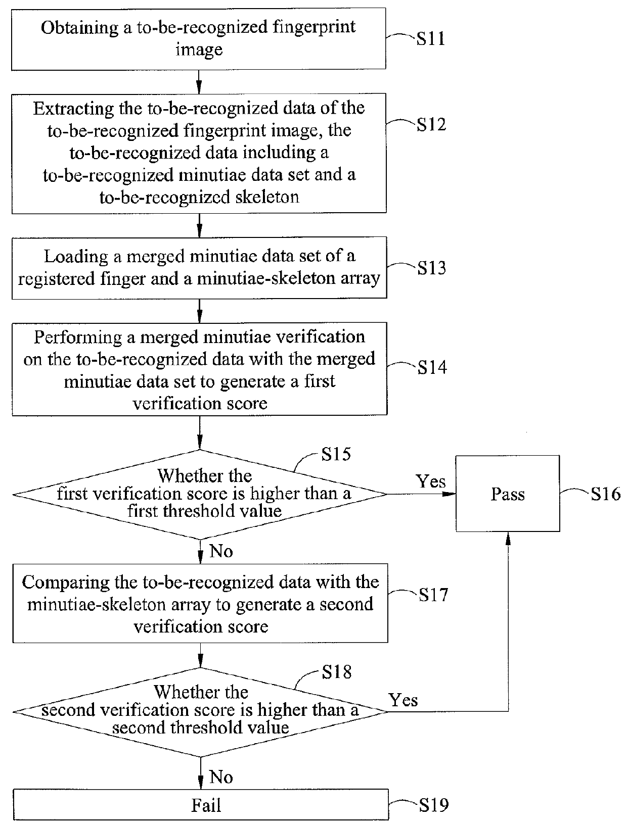
[0040]The to-be-recognized fingerprint image V1 is obtained, and the merged minutiae verification is performed on the to-be-recognized fingerprint image V1 with the registered finger R. The first verification score generated from the merged minutiae verification is higher than the first threshold value, therefore, the to-be-recognized fingerprint image V1 passes the verification.

[0041](1) The first threshold value M_TH=70.

[0042](2) The first verification score MM (MR, (mv1, sv1))=150>M_TH.

[0043](3) The verification passes, and the first verification score is 150.

example 2

[0044]The to-be-recognized fingerprint image V2 is obtained, and the to-be-recognized fingerprint image V2 fails to pass the merged minutiae verification. Then, the minutiae-skeleton verification is performed. The minutiae-skeleton array comprises three element; N=3. The second try of the minutiae-skeleton verification on the second element of the array passes the verification since the second verification score for the second element of the array is higher than the second threshold value. Here, Example 2 is explained with reference to FIG. 9 (A) to FIG. 9(C). FIG. 9 (A) is the registered fingerprint image, FIG. 9 (B) is the registered skeleton SR2, FIG. 9 (C) is the registered skeleton SR2 after rotation, FIG. 9 (D) is the to-be-recognized fingerprint image, FIG. 9 (E) is the to-be-recognized skeleton SV2, FIG. 9 (F) is the dilated to-be-recognized skeleton SV2, and FIG. 9 (G) is the overlaid image generated by overlaying the images in FIG. 9 (C) and FIG. 9 (F).

[0045](1) The first ...

example 3

[0050]The to-be-recognized fingerprint image V3 is obtained, which fails to pass the merged minutiae verification performed with the registered finger R, and all of the second verification scores generated from the three tries of the minutiae-skeleton verification N=3 are smaller than the second threshold value, which means the to-be-recognized fingerprint image V3 fails to pass the verification. Here, Example 3 is explained with reference to FIG. 10 (A) to FIG. 10(G). FIG. 10 (A) is the registered fingerprint image, FIG. 10 (B) is the registered skeleton SR3, FIG. 10 (C) is the registered skeleton SR3 after rotation, FIG. 10 (D) is the to-be-recognized fingerprint image, FIG. 10 (E) is the to-be-recognized skeleton SV3, FIG. 10 (F) is the dilated to-be-recognized skeleton SV3, and FIG. 10 (G) is the overlaid image generated by overlaying the images in FIG. 10 (C) and FIG. 10 (F).

[0051](1) The first threshold value M_TH=70, and the second threshold value t_TH=50.

[0052](2) The first ...


PUM


Abstract

A fingerprint recognition method includes the following steps: obtaining a to-be-recognized fingerprint image of a to-be-recognized finger; extracting to-be-recognized data of the to-be-recognized fingerprint image, the to-be-recognized data including a to-be-recognized minutiae data set and a to-be-recognized skeleton; loading a minutiae-skeleton array of a registered finger, the minutiae-skeleton array including a plurality of elements, each of the plurality of elements including a registered minutiae data set and a registered skeleton; performing minutiae-skeleton verification on the to-be-recognized data and the minutiae-skeleton array to generate a verification result.

Description

CROSS-REFERENCE TO RELATED APPLICATION[0001]This application claims the priority benefit from U.S. provisional Application No. 61 / 912,265, filed on Dec. 5, 2013, the disclosure of which is incorporated herein in its entirety by reference.BACKGROUND OF THE INVENTION[0002]1. Field of the Invention[0003]The present invention relates to a fingerprint recognition method and device thereof, in particular with respect to a fingerprint recognition method and device thereof which performs fingerprint verification by using a merged minutiae data set and a minutiae-skeleton array.[0004]2. Description of the Related Art[0005]In order to meet the demand of personal identification recognition, recently, many biometrics recognition methods such as fingerprint recognition, retina recognition, face recognition, voice recognition and so on have been developed. The fingerprint recognition method is widely applied to various consumer electronic products, such as notebooks, smartphones, personal digital...

Claims


Application Information

Patent Timeline
IPC IPC(8): G06K9/00
CPCG06K9/00073G06V40/1365G06V30/2504G06V40/1353
Inventor CHIANG, YUAN-LINCHENG, YU-CHUN
Owner EGIS TECH
Why Eureka
Try Eureka