Eureka AIR delivers breakthrough ideas for toughest innovation challenges, trusted by R&D personnel around the world.

Thermoelectric Device

Active Publication Date: 2016-02-04
VECARIUS
View PDF5 Cites 22 Cited by
  • Summary
  • Abstract
  • Description
  • Claims
  • Application Information

AI Technical Summary

Benefits of technology

The present patent is about new designs of a thermoelectric device that can overcome issues with existing thermoelectric systems. These designs can be used for high-temperature thermoelectric generation and fluid conditioning. The unique features of the patent make the device more efficient, portable, versatile, and cost-effective.

Problems solved by technology

Conventional TEG systems pose challenges, particularly at high temperatures due to thermal expansion effects, resulting in difficulties in reliability, packaging (i.e. size, weight, versatility), and performance.
Furthermore, these challenges often lead to system designs that require increased levels of complexity to be viable, which also increases cost.

Method used


Image

  • Thermoelectric Device
  • Thermoelectric Device
  • Thermoelectric Device

Examples


Embodiment Construction

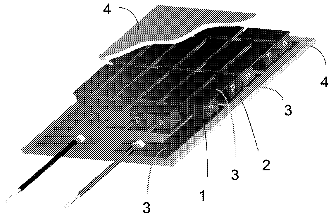
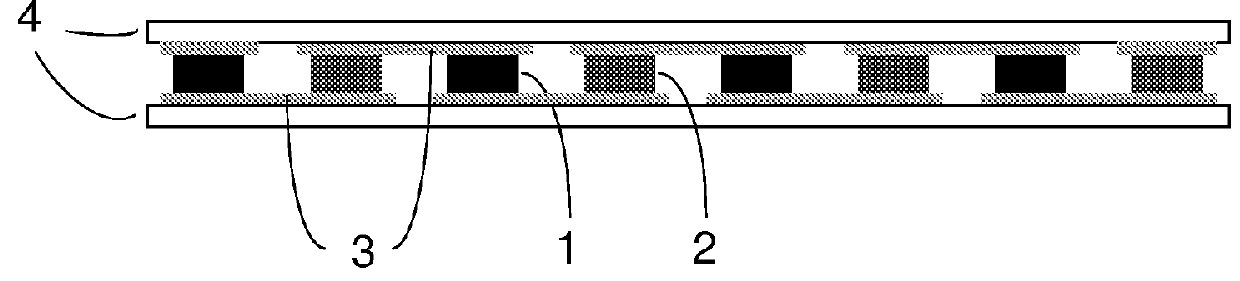
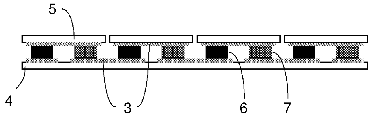
[0045]The present disclosure relates to thermoelectric devices that may have an architecture which may be useful for a variety of applications, including thermoelectric generation (e.g., exhaust system from a combustion engine including, but not limited to those in vehicles) and fluid conditioning (e.g. heating and cooling of fluids). Various embodiments of thermoelectric devices in accordance with the present disclosure are able to perform thermoelectric conversion between thermal and electrical energy.

[0046]Certain embodiments of thermoelectric devices and systems described herein are capable of operating reliably, for example, as thermoelectric generators (TEGs), drawing energy from a thermal gradient provided, at least in part, from a high temperature fluid (e.g., up to 700 degrees C. and higher) located on a “hot-side” of the device. As such, embodiments of the present disclosure may allow for large temperature differences to exist between the “hot-side” and the “cold-side” of ...


PUM


Abstract

The present disclosure relates to thermoelectric devices useful for a range of thermoelectric applications (e.g., high temperature thermoelectric generation, fluid conditioning). Thermoelectric devices may include one or more heat exchangers (e.g., coolant heat exchanger(s)) and one or more thermoelectric layers adjacent to the heat exchanger(s). An enclosure may surround the thermoelectric layer(s) and heat exchanger(s), providing a barrier from outside fluid (e.g., hot fluid flow). The enclosure may conduct heat between the outside surroundings and the thermoelectric layer(s). The heat exchanger(s) may be spaced from and movable or slidable relative to the enclosure, which may accommodate for certain thermal expansion effects. The enclosure may include a conformable surface adapted to conform substantially to the shape of the thermoelectric layer(s) (e.g., when a vacuum is applied). One or more thermally conductive members (e.g., fins) may extend from the conformable enclosure. Various embodiments of a thermal switch are also described.

Description

FIELD[0001]Aspects of the present disclosure relate generally to apparatuses and methods that may be used in cooperation with thermoelectric systems.DISCUSSION OF RELATED ART[0002]Thermoelectric generators are devices that convert thermal energy, arising from a temperature difference, into electrical energy using a phenomenon called the “Seebeck effect.”[0003]Due to their ability to convert thermal energy produced by a temperature difference directly into electricity within a compact solid-state form, thermoelectrics have received a significant amount of attention. For instance, thermoelectrics may be useful for efficiently recovering waste heat at high temperatures from energy-intensive platforms, such as combustion engines in automobiles.[0004]Conventional TEG systems pose challenges, particularly at high temperatures due to thermal expansion effects, resulting in difficulties in reliability, packaging (i.e. size, weight, versatility), and performance. Furthermore, these challenge...

Claims


Application Information

Patent Timeline
IPC IPC(8): H01L35/32H01L35/30
CPCH01L35/30H01L35/32F01N5/025Y02T10/12H10N10/17H10N10/13
Inventor CASEY, STEVEN
Owner VECARIUS
Why Eureka
Eureka Blog
Learn More