
Modular Tray Ampoule

a module tray and ampoule technology, applied in the field of vaporizers, can solve the problems of increasing consumption, increasing the cost of current vaporizers, and vaporizer vessel designs having manufacturing and ongoing service issues, so as to increase the amount of solids, increase the amount of consumption, and be easily accessible and configurable for installation

Active Publication Date: 2019-01-31
ENTEGRIS INC
View PDF0 Cites 5 Cited by
  • Summary
  • Abstract
  • Description
  • Claims
  • Application Information

AI Technical Summary

Benefits of technology

The patent text describes a new system for vaporizing precursors in semiconductor manufacturing. The system is designed to be easily installed and customized for different manufacturing facilities. The system includes a modular tray and a base module that can be easily adjusted for different applications. The trays can be sealed and have built-in heating elements, allowing for efficient heating and consistent output. The system also includes a lid module that can be easily customized. Overall, the system provides improved efficiency, flexibility, and consistency in the vaporization process.

Problems solved by technology

New technology applications have increased the amount of solid chemistries being used in wafer manufacturing and have increased the amount of consumption.
The current vaporizer vessel designs have manufacturing and ongoing service issues despite being commercially successful products.
The current vaporizers can be costly to build and may be challenging to assemble outside of a vendor's manufacturing facility.
In some cases, the vaporizer design itself can be rigid and may not lend itself to application specific changes or modifications requested by a customer.
If a customer requires some level of customization, such as a new valve, a different vaporizer vessel height, or a different precursor material fill amount, costly changes may have to be made by engineering and manufacturing to fulfill these requests.
Customers ordering an ampoule or vaporizer vessel that can fit their existing capital equipment or wanting to change ampoule vendors may be limited by their current installation layout.
Current designs rely on convection ovens or heating blankets which have inherent problems and can present heating uniformity challenges due to the multiple components (vessel body, base and lid members, each support tray within the vessel body, etc.).
Understanding the ampoule's overall response to heat inputs is another situation that customers spend significant time on.

Method used


Image

  • Modular Tray Ampoule
  • Modular Tray Ampoule
  • Modular Tray Ampoule

Examples


Embodiment Construction

[0015]Following are more detailed descriptions of various related concepts related to, and embodiments of, methods and apparatus according to the present disclosure. It should be appreciated that various aspects of the subject matter introduced above and discussed in greater detail below may be implemented in any of numerous ways, as the subject matter is not limited to any particular manner of implementation. Examples of specific implementations and applications are provided primarily for illustrative purposes.

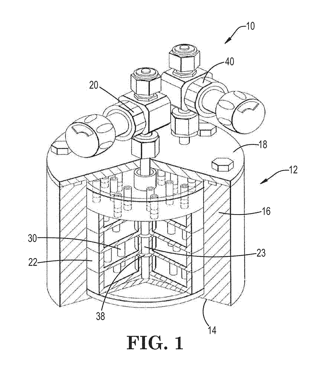
[0016]Referring to the Figures, FIG. 1 is perspective view of a prior art vaporizer 10 of a general type. The vaporizer 10 comprises a vessel body 12 fabricated of a suitable heat-conducting material. Vessel body 12 comprises a floor 14 and circumscribing sidewall 16 that together form an interior volume of the vessel. Vessel body 12 can have any shape that facilitates an even flow of carrier gas through the interior volume thereof. In one embodiment, the vessel has a cylindr...


PUM

PropertyMeasurementUnit
Diameteraaaaaaaaaa

Abstract

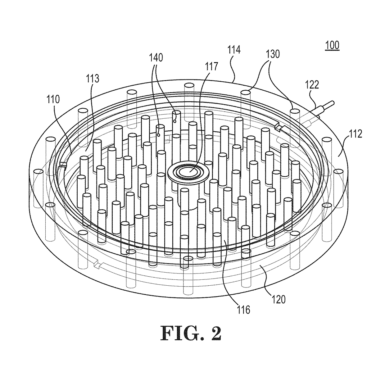
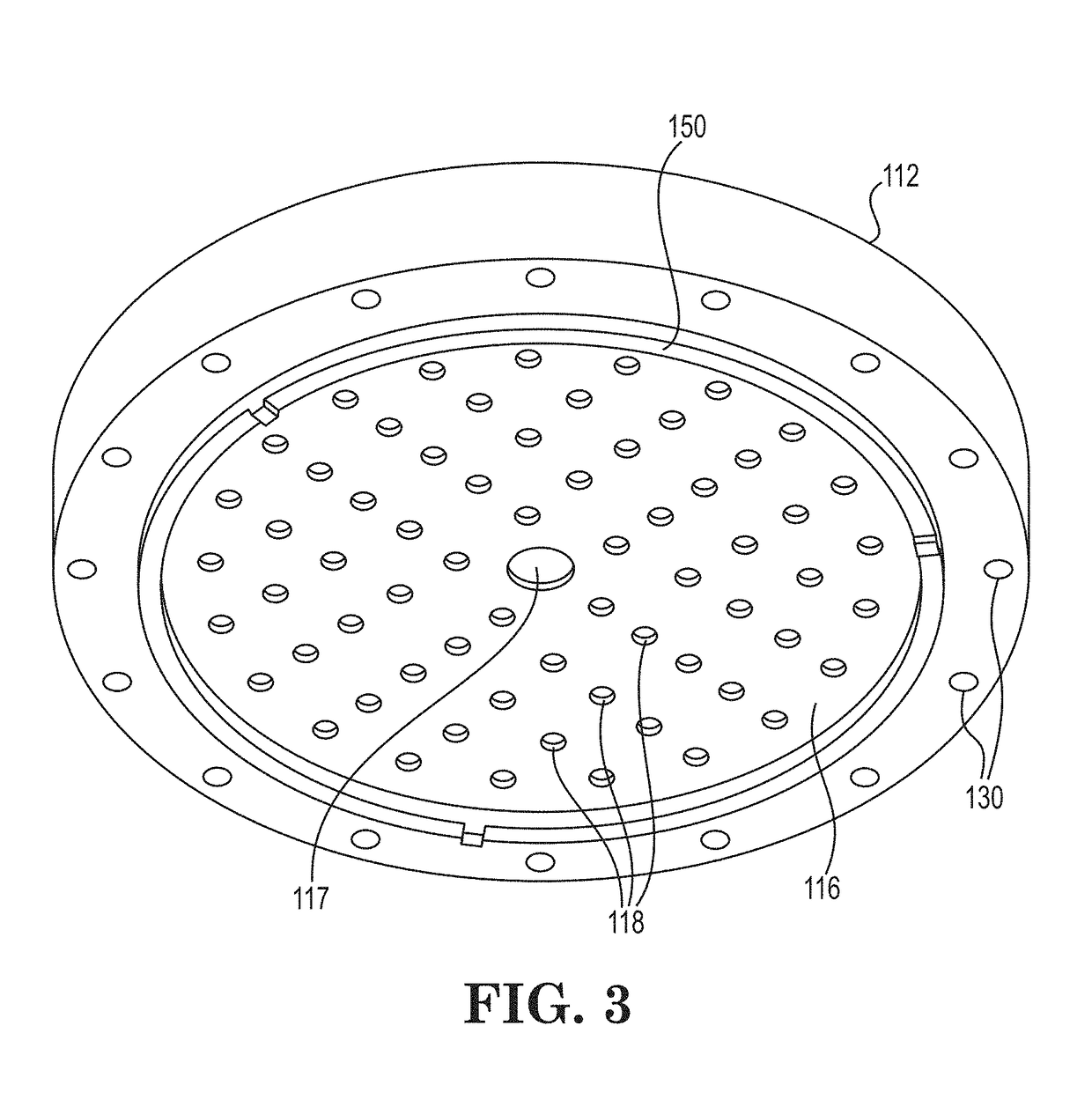
The invention is directed to a configurable vaporizer or ampoule assembly that uses a configurable vessel body, assembled from one or more support tray modules with their own individual heating assemblies or heater members, bounded by a base member and a lid member to form the whole ampoule. This eliminates the need for the prior art ampoule body that normally holds the support trays and was used to heat each of the support trays from the exterior surface using heating jackets or the like.

Description

CROSS-REFERENCE TO RELATED APPLICATIONS[0001]This application claims the benefit under 35 USC 119 of U.S. Provisional Patent Application No. 62 / 538,118, filed Jul. 28, 2017, the disclosure of which is hereby incorporated herein by reference in its entirety for all purposes.FIELD OF INVENTION AND BACKGROUND[0002]The present disclosure relates to vaporizers useful in volatilizing solid precursors to provide precursor vapor to a precursor vapor-utilizing process system such as a vapor deposition chamber or an ion implanter for manufacturing of semiconductor products, flat-panel displays, solar panels, and the like.[0003]In the use of solid-phase precursors to supply precursor vapor for vapor-utilizing applications, a wide variety of vaporizers have come into use. Such vaporizers may comprise a vessel and cover defining an enclosed interior volume in which a solid phase precursor may be stored and subsequently subjected to volatilization conditions to effect sublimation or vaporization ...

Claims


Application Information

Patent Timeline
IPC IPC(8): C23C16/448C23C16/455
CPCC23C16/4483C23C16/45544C23C16/18C23C16/08
Inventor HODGES, JORDANTHOMAS, JACOB
Owner ENTEGRIS INC
Learn More