Waterproof connector

Active Publication Date: 2016-02-04
SUMITOMO WIRING SYST LTD
View PDF5 Cites 7 Cited by
  • Summary
  • Abstract
  • Description
  • Claims
  • Application Information

AI Technical Summary

Benefits of technology

[0009]However, according to the present invention, a situation where the rear ring portion is flipped or buckled as the receptacle moves is avoided since the rear ring portion of the seal ring is radially sandwiched between the protrusion of the first housing and the housing main body. In addition, since the protrusion is covered with the opening edge portion of

Problems solved by technology

Thus, if the rear end part of the seal member extends long as described above, it may be flipped or buckled along a

Method used


Image

  • Waterproof connector
  • Waterproof connector
  • Waterproof connector

Examples


Example

[0021]Preferred embodiments of the present invention are described below.

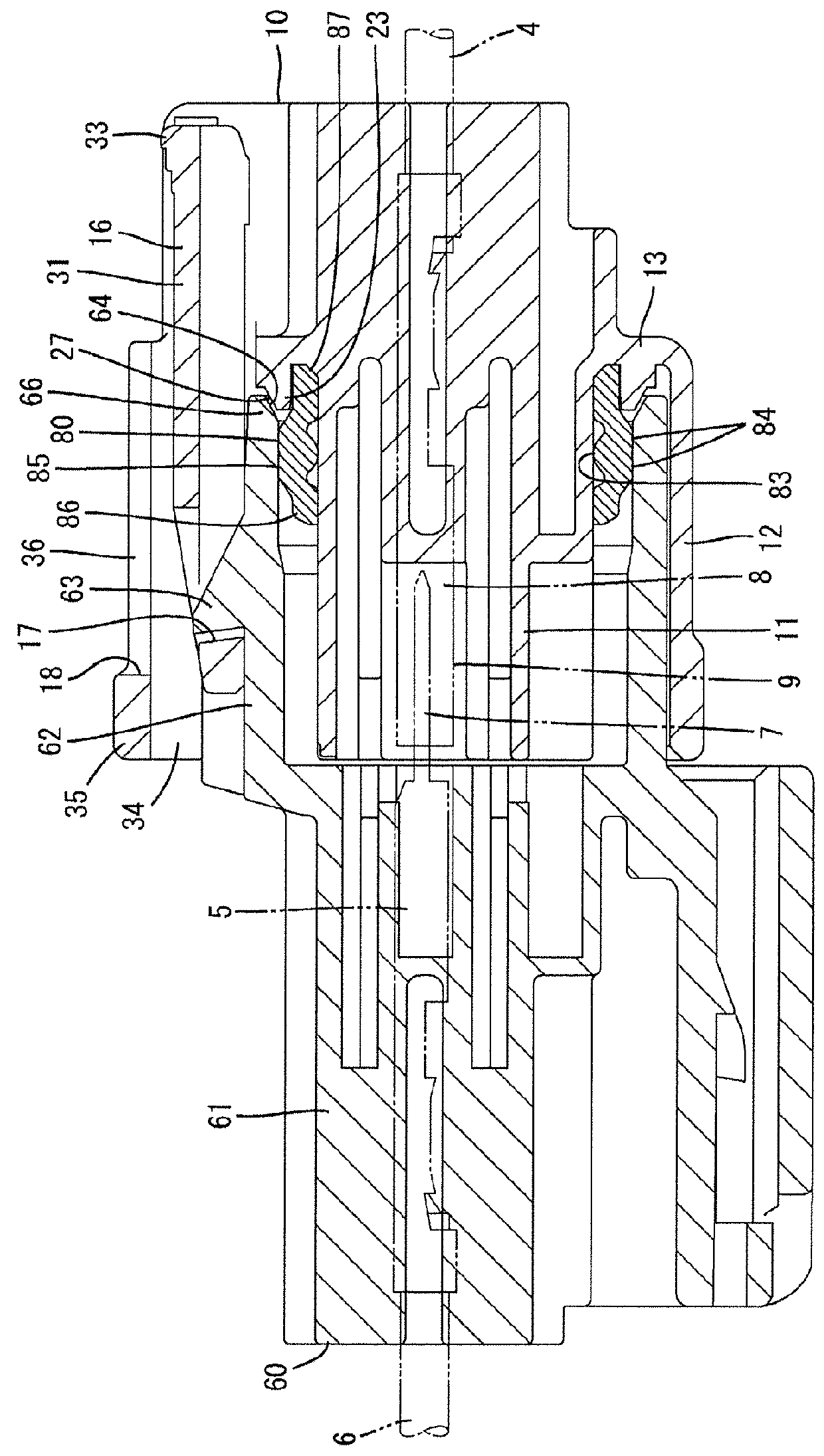
[0022]The rear ring portion is set longer in the front-back direction than the front ring portion. According to such a configuration, a merit of applying the present invention is large since there is a higher possibility that the rear ring portion is flipped or buckled.

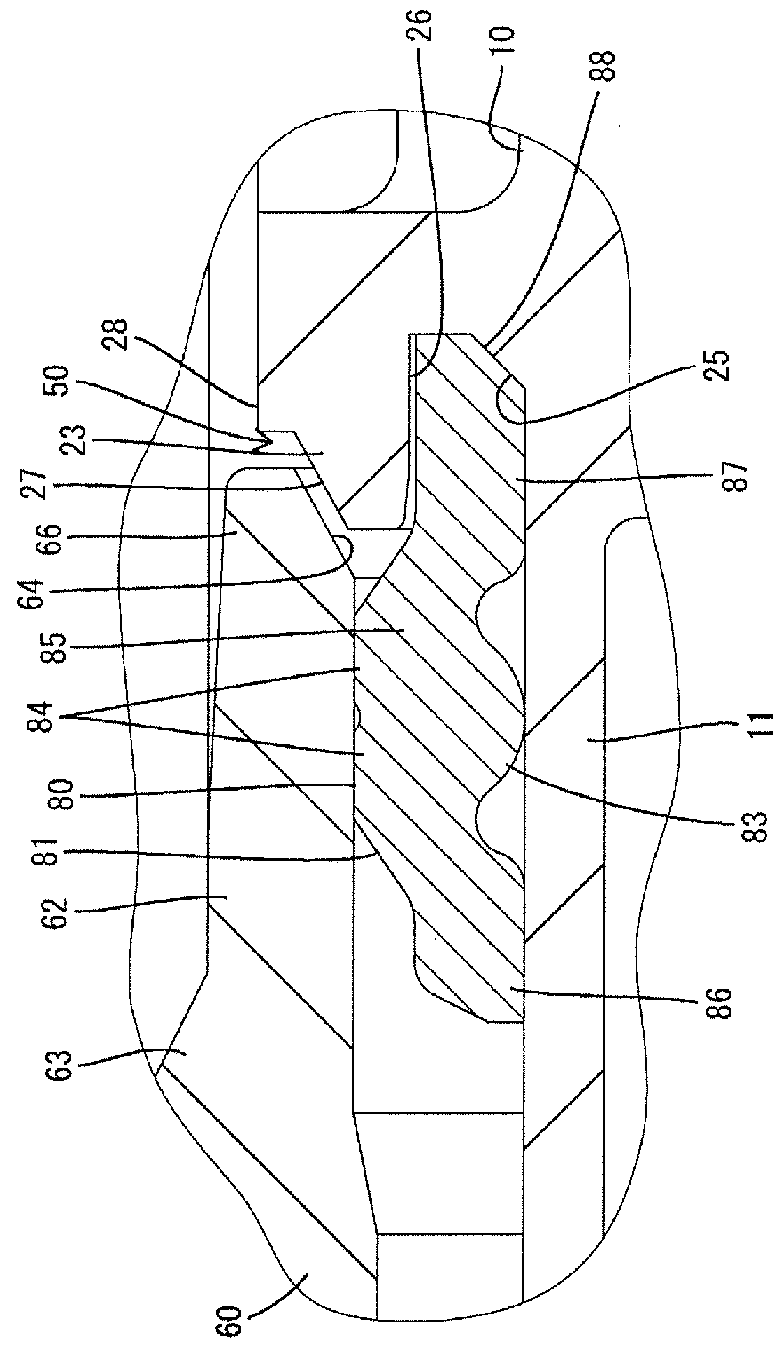
[0023]An inner surface of the protrusion serves as a restricting surface arranged at a position facing the outer surface of the housing main body and capable of preventing the rear ring portion from being flipped up by coming into contact with the rear ring portion from an outer side. The rear ring portion is reliably prevented from being flipped up by the contact thereof with the restricting surface of the protrusion.

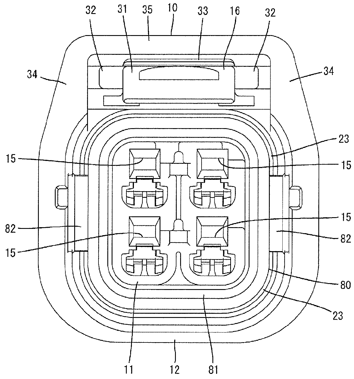
[0024]The first housing includes an outer side wall surrounding the housing main body and a radially extending coupling portion coupling the outer side wall and the housing main body, a fitting space into which the receptacle is to ...


PUM


Abstract

A seal ring (80) is fit on an outer surface of a housing main body (11) and rests on a resting portion. When a receptacle (62) is fit externally on the housing main body (11), outer peripheral lips (84) of the seal ring (80) closely contact an inner surface of the receptacle (62). The seal ring (80) includes front and rear rings (86, 87) extending in a front-back direction at opposite front and rear sides of the outer peripheral lips (84). The rear ring (87) is longer in the front-back direction than the front ring (86). A first housing (10) includes a protrusion (23) for radially sandwiching the rear ring (87) between the protrusion (23) and the housing main body (11). When the receptacle (62) is fit externally on the housing main body (11), the protrusion (23) is covered with an opening portion (66) of the receptacle (62).

Description

BACKGROUND[0001]1. Field of the Invention[0002]The present invention relates to a waterproof connector.[0003]2. Description of the Related Art[0004]A waterproof connector disclosed in Publication of Japanese Patent No. 4193711 includes a pair of male and female housings connectable to each other. Out of these housings, the female housing includes an inner tube portion and an outer tube portion surrounding the inner tube portion. An annular seal member is fitted on the outer surface of the inner tube portion. On the other hand, the male housing includes a tubular receptacle externally fittable on the inner tube portion from front. Further, a plurality of lips are circumferentially provided one after another in a front-back direction on the seal member, and each lip is resiliently held in close contact with the inner surface of the receptacle to seal between the two housings when the two housings are connected.[0005]A long and narrow rear end part of the seal member may extend backwar...

Claims


Application Information

Patent Timeline
IPC IPC(8): H01R13/52
CPCH01R13/5202H01R13/5219
Inventor IIHOSHI, SHINJI
Owner SUMITOMO WIRING SYST LTD
Why Eureka
Try Eureka