Optical pressure sensor assembly

a sensor and optical technology, applied in the field of optical pressure sensing/sensor assemblies, can solve the problems of reducing blood circulation to the brain and heart, affecting the blood circulation to the arms, legs, stomach and kidneys, and increasing the risk of stroke and heart diseas

Active Publication Date: 2016-02-11
AVINGER
View PDF12 Cites 48 Cited by
  • Summary
  • Abstract
  • Description
  • Claims
  • Application Information

AI Technical Summary

Benefits of technology

The present technology describes different ways how we can detect when someone has been threatened by fire or other threats. It involves operating a device called a sensor that emits lights towards them while they are being protected against these attacks. When there're no harming substances nearby, it sends signals back wirelessly around their body. This signal helps protect people who have gone wrong during fires.

Problems solved by technology

The technical problem addressed in this patent text is the need for an optical pressure sensor that can be easily integrated or incorporated into existing vascular treatment devices, such as atherectomy devices, to assess the pressure gradient across an occlusion and determine if interventional treatment is beneficial or not. Existing electrical pressure sensors have limitations such as calibration drift and electrical interference, which can affect accuracy, and it is challenging to include additional components for a pressure sensor without detracting from the optimal size of the devices.

Method used


Image

  • Optical pressure sensor assembly
  • Optical pressure sensor assembly
  • Optical pressure sensor assembly

Examples


Embodiment Construction

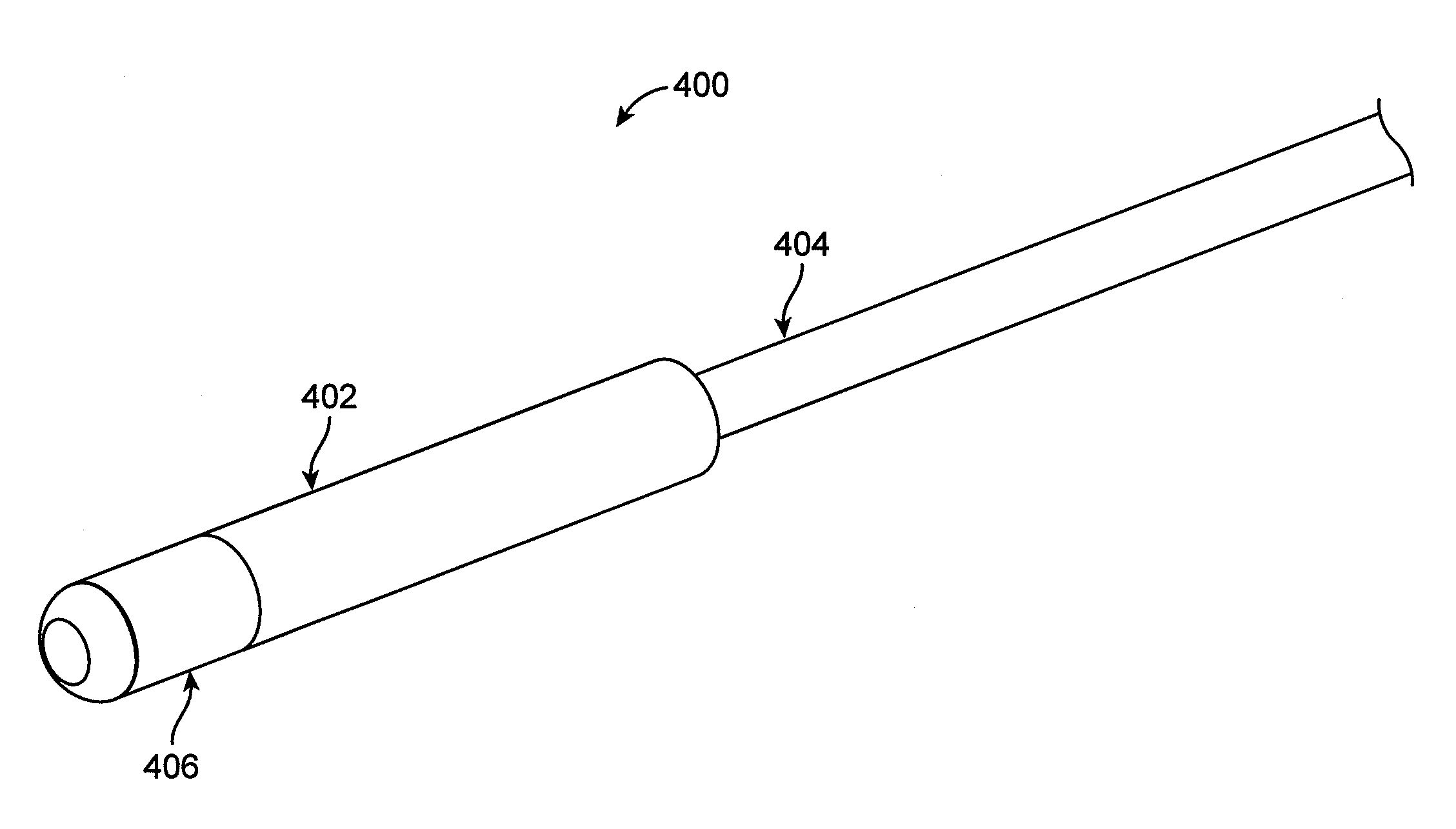
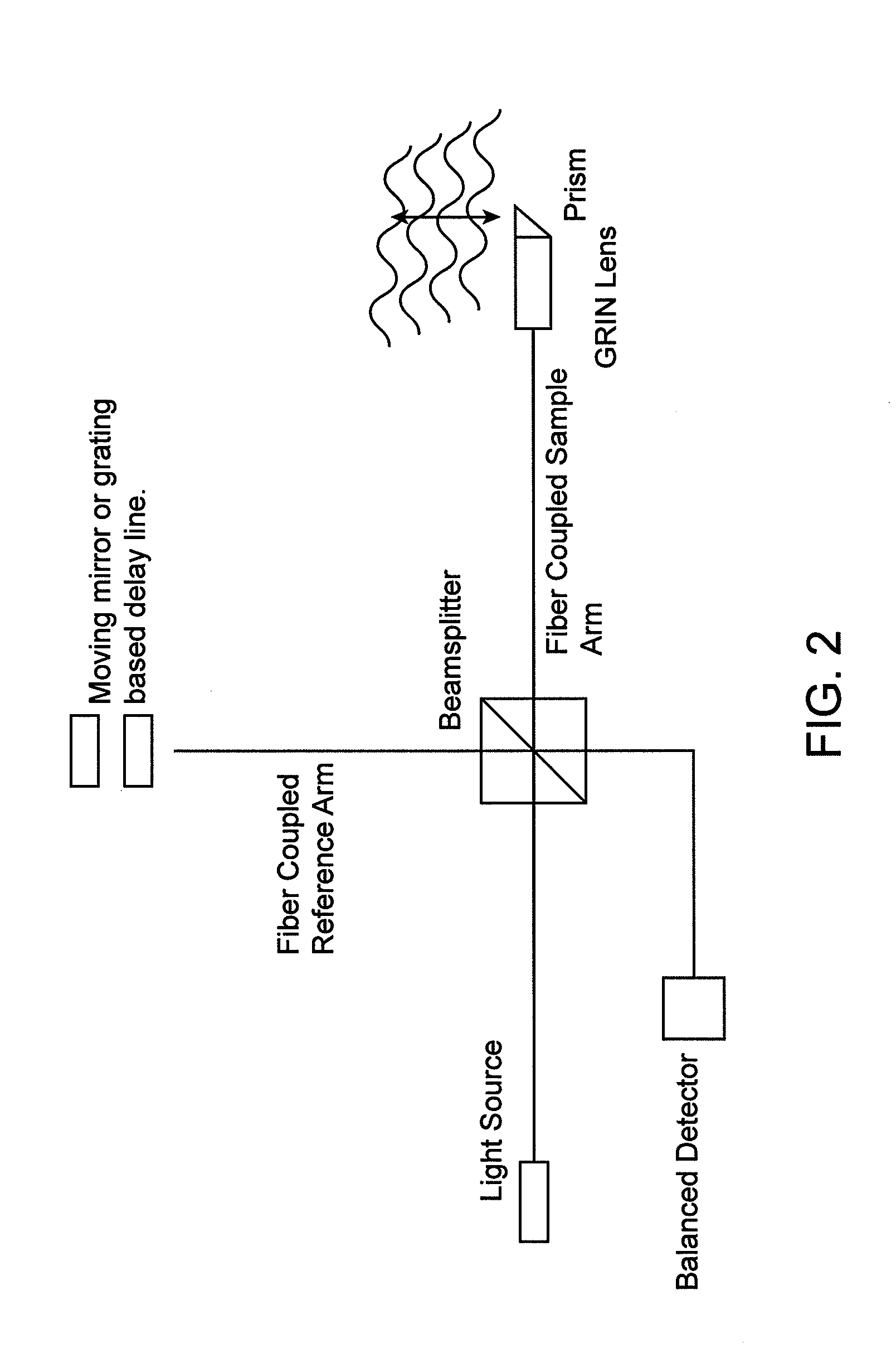
[0074]Embodiments described herein provide for optical pressure sensor assemblies that utilize the basic framework of an imaging system to provide pressure measurements. Although any suitable optical or imaging modality can be used with the contemplated invention(s), optical coherence tomography (OCT) is described as an illustrative example of how the invention is compatible with an imaging system. As such, a general overview of OCT is provided below, followed by a description of the optical pressure sensor assemblies that can be used with OCT or other imaging systems. It is to be appreciated, that the OCT discussion is for illustration purposes and not limiting the invention to any specific imaging modality.

I. OCT System General Overview

[0075]OCT has been proposed as one technique that may be particularly helpful for imaging regions of tissue, including within a body lumen such as a blood vessel. At a basic level, OCT relies on the fact that light traveling from a source and scatte...


PUM


Abstract

Optical pressure sensor assemblies that can be used with existing catheters and imaging systems. Pressure sensors may be compatible with atherectomy and occlusion-crossing catheters, where intravascular pressure measurements at various vessel locations are needed to determine treatment efficacy. The pressure sensors may employ an optical pressure measurement mechanism using optical interferometry, and may be integrated with existing imaging modalities such as OCT. The pressure sensor assemblies may include a movable membrane that deflects in response to intravascular pressure; an optical fiber that transmits light to the movable membrane and receives light reflected or scattered back from the movable membrane into the fiber; and a processor or controller configured to determine the distance traveled by the light received in the fiber from the movable membrane, where the distance traveled is proportional to the intravascular pressure exerted against the membrane.

Description


Claims


Application Information

Patent Timeline
Owner AVINGER
Why Eureka
Try Eureka