Implant masking and alignment

Active Publication Date: 2016-02-11
INTEVAC
View PDF4 Cites 7 Cited by
  • Summary
  • Abstract
  • Description
  • Claims
  • Application Information

AI Technical Summary

Benefits of technology

[0009]According to disclosed embodiments, the substrate is precision aligned (optically or by other means) to a reference edge in atmosphere, and then it self-aligns to multiple masks with built in guide bar as it travels under each mask. This approach offers multiple advantages. For example, precision alignment can be done in atmosphere where a lot more options and less expensive solutions are available. The masks can be fixed and don't need to come out of vacuum for aligning each successive mask. Also, since the masks can stay s

Problems solved by technology

This is beneficial since typically masks are f

Method used


Image

  • Implant masking and alignment
  • Implant masking and alignment
  • Implant masking and alignment

Examples


Example

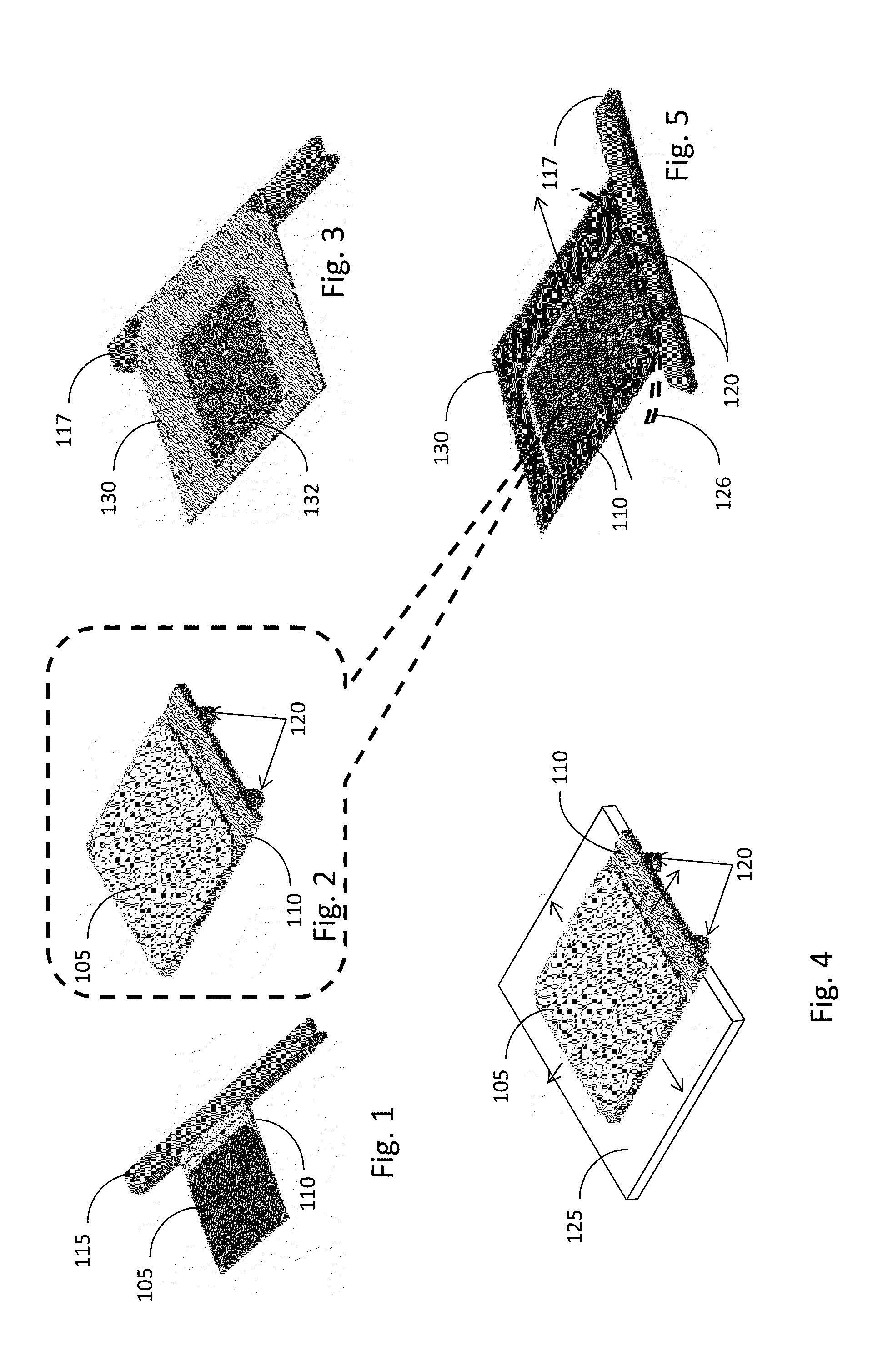
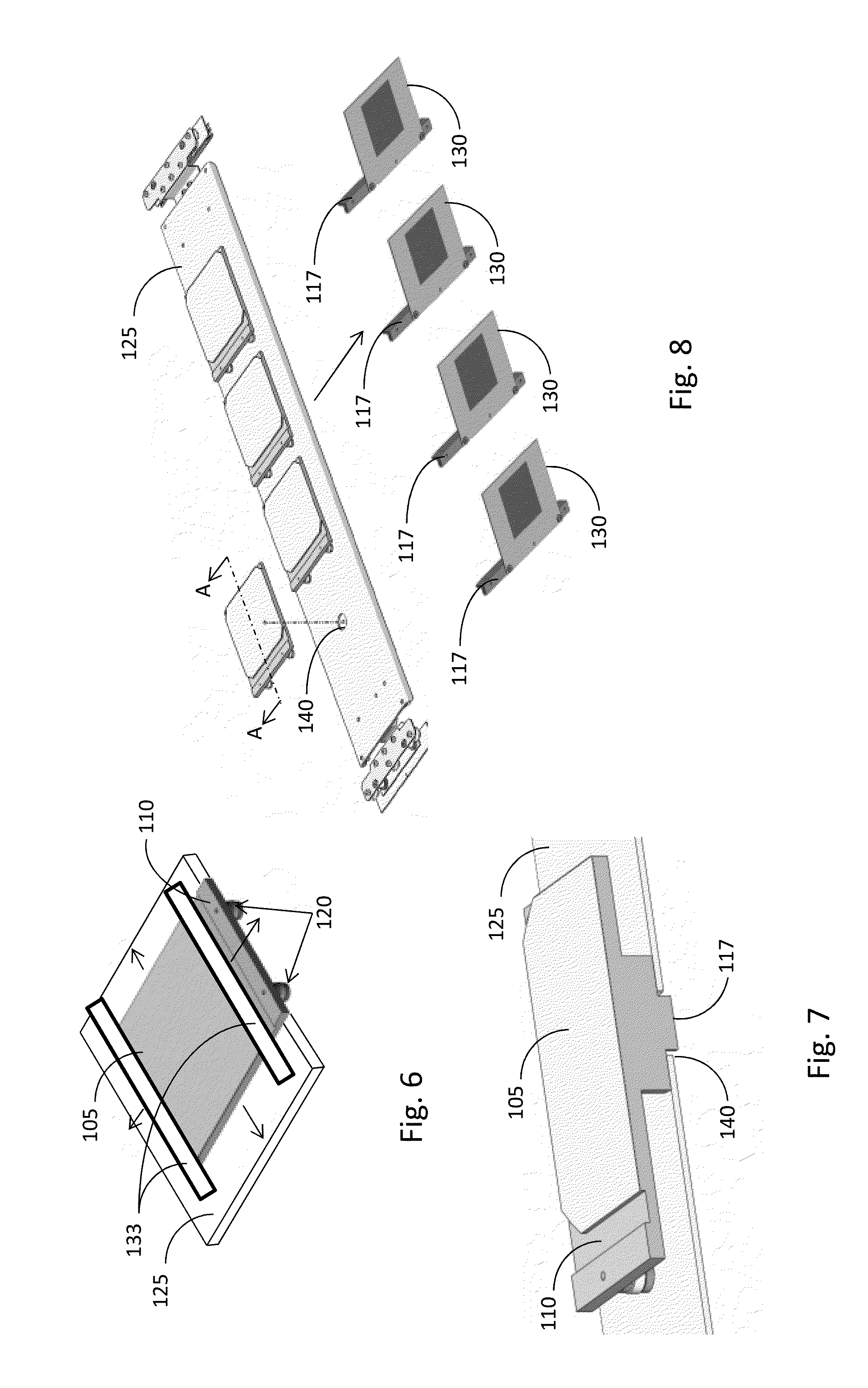
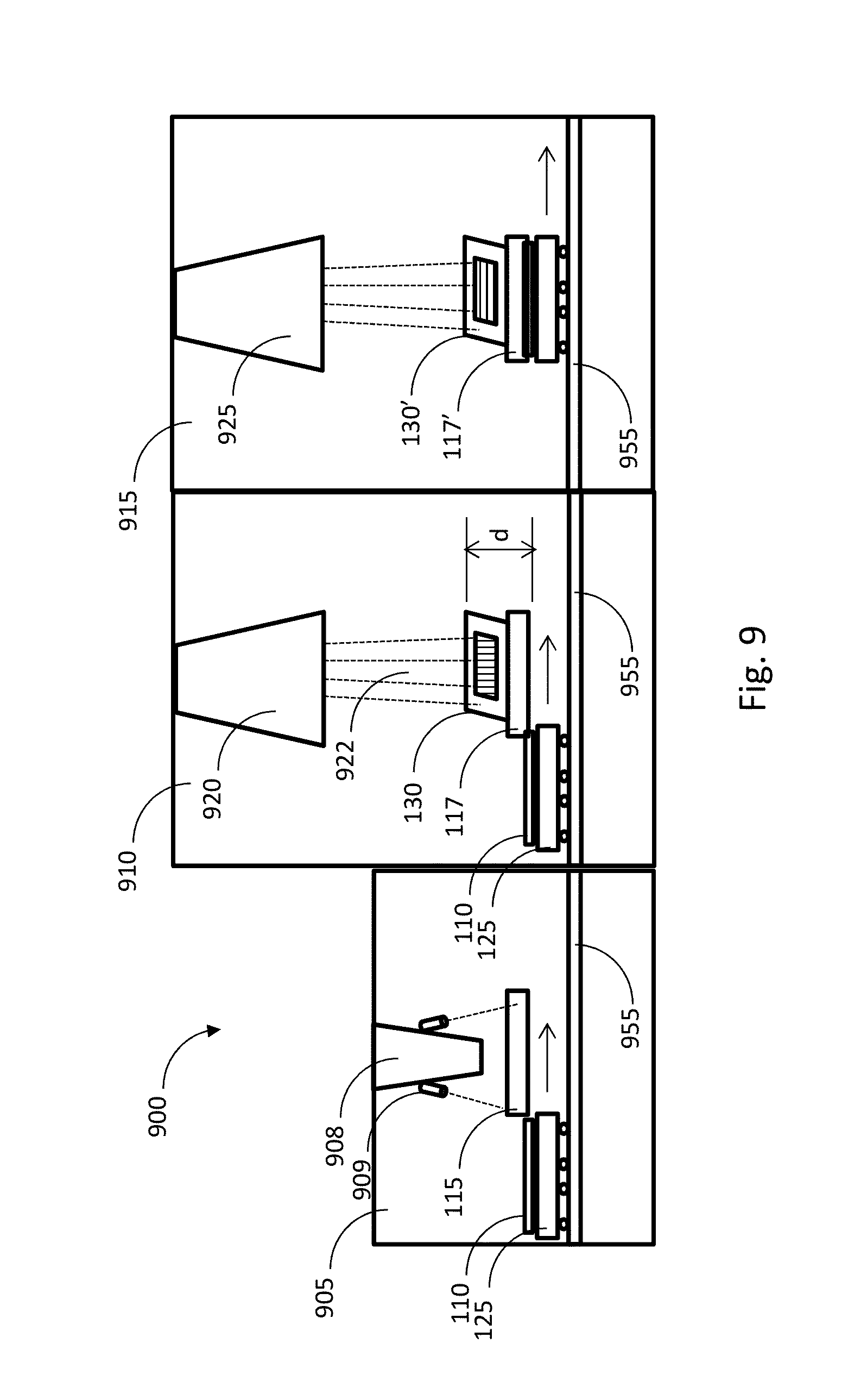
[0023]According to various embodiments, the substrate sits on an electro static chuck or other susceptor or holder (hereinafter referred to simply as holder, to encompass any means of supporting and chucking a substrate) and the holder travels on a carrier in and out of the vacuum system. The substrate holder has multiple alignment features and / or rollers on one or multiple sides of the holder, which are brought into contact with a precision reference edge (either in atmosphere or in vacuum). The alignment feature is magnetically, mechanically or otherwise brought in precise alignment to the precision reference edge, so that the alignment feature is pressed against the edge. In one embodiment, the alignment feature comprises rollers, and the roller's tangents adhere to alignment edge of an alignment bar. The substrate is precision-aligned (for example optically) to the fixed reference edge of the holder, and hence to the tangent of the holder's alignment feature, e.g., the rollers. ...


PUM


Abstract

System and method to align a substrate under a shadow mask. A substrate holder has alignment mechanism, such as rollers, that is made to abut against an alignment straight edge. The substrate is then aligned with respect to the straight edge and is chucked to the substrate holder. The substrate holder is then transported into a vacuum processing chamber, wherein it is made to abut against a mask straight edge to which the shadow mask is attached and aligned to. Since the substrate was aligned to an alignment straight edge, and since the mask is aligned to the mask straight edge that is precisely aligned to the alignment straight edge, the substrate is perfectly aligned to the mask.

Description

RELATED APPLICATION[0001]This application claims priority from U.S. Provisional Application No. 62 / 033,104, which was filed on Aug. 5, 2014, the entire disclosure of which is incorporated herein by reference.BACKGROUND[0002]1. Field[0003]This disclosure relates to fabrication of semiconductor devices and, more specifically, to the use of masks during the fabrication process, such as masked ion implant process.[0004]2. Related Arts[0005]Typically implanted pattern has stringent requirements for accuracy of features, such as location and spacing of implanted lines. The lines may be, for example, implant for increase conductance under metal fingers used to draw current from solar cells. These lines may be very thin and very dense (i.e., narrow pitch), requiring high accuracy of the implant. Many times more than one implanted pattern is needed on the same substrate. In that case, high level of accuracy needs to be maintained not only in one implant step but through multiple implant step...

Claims


Application Information

Patent Timeline
IPC IPC(8): H01J37/20H01J37/18H01J37/317
CPCH01J37/20H01J37/3171H01J2237/31701H01J2237/202H01J37/185H01J37/3045H01J2237/2007H01J2237/204H01J2237/31711
Inventor ADIBI, BABAKPRABHAKAR, VINAYBLUCK, TERRY
Owner INTEVAC
Why Eureka
Try Eureka