RFID system for identification of cryogenic straws

a technology of rfid system and cryogenic straw, which is applied in the direction of protective material radiating elements, instruments, laboratory glassware, etc., can solve the problem of not working at room temperature, and achieve the effects of reducing the number of rfid systems

Active Publication Date: 2019-01-03
VIKING GENETICS FMBA
View PDF5 Cites 13 Cited by
  • Summary
  • Abstract
  • Description
  • Claims
  • Application Information

AI Technical Summary

Benefits of technology

[0009]In the previously known solutions operating at a low frequency e.g. 125 kHz or 13 MHz there would be a need for a coil wound around a ferrite core, which requires considerable space in relation to a thin cryogenic straw having a diameter of e.g. 2 mm. In contrast, the present invention preferable operates at ultra-high frequencies, which means that the antenna can be designed as a thin thread / rod. In a preferred embodiment the antenna is cast into the wall of the straw, which provides for a cheap, light and robust solution. Using higher frequencies has the advantage that larger bandwidth can be used, which gives a faster response as well as higher data transfer per given time unit. This enables reading of readings of IDs for a high amount of straws within a short period of time. Furthermore it has the advantage that it has a relatively long reach and that the antenna can be made thin and generally small in size. Preferably the antenna is implemented as a conductive thread / rod having a diameter of less than 0.1 mm. Alternatively the antenna may be implemented as a thin sheet or hollow rod, preferably made of a metal. The antenna may also be embodied in the shape of a thin film configured to be attached to the inside or outside of the cryogenic straw. In one embodiment the film has a thickness of less than 20 μm, more preferably less than 10 μm, even more preferably less than 5 μm. Generally, the straw / rod / film may be as thin as 10 μm or even 5 μm. Preferably, the film is made of an electrically conductive material, such as a metallic material. The film may have the shape of a hollow cylinder having a thin sidewall and an inner diameter substantially equal to the outer diameter of the straw such that is fits on the outside of the straw, alternatively an outer diameter substantially equal to the inner diameter of the straw such that is fits on the inside of the straw. As an alternative to casting the antenna into the cylindrical wall of the straw, the antenna may be placed on the inside or outside of the straw. Preferably, the antenna extends in the longitudinal direction of the straw.
[0010]The antenna may be incorporated into the cryogenic straw. In one embodiment of the presently disclosed radio-frequency identification system, the antenna extends along the cryogenic straw, such as integrated in the cryogenic straw, and protrudes upwards such that a first portion of the antenna is integrated in the cryogenic straw and a second portion protrudes upwards outside the cryogenic straw in substantially the longitudinal direction of the cryogenic straw. This solution enables a possibility that the sample can stay in the cryogenic fluid while a portion of the antenna operates above the surface of the fluid. Upwards in this context refers to a placement in which the straw is placed in a substantially vertical position i.e. having one lower and one upper end, and the antenna extends and protrudes beyond the upper end of the cryogenic straw. This embodiment has the advantage that the antenna can be designed such that it protrudes above the surface of the liquid nitrogen, which improves the conditions for receiving and transmitting radio waves. The integrated circuit may also be integrated in a sealing element configured to be sealingly engaged inside the cryogenic straw, wherein the straw is preferably sealed in the lower end. The upwardly protruding antenna may be attached or integrated in a handle or shaft, the assembly arranged such that the cryogenic straw can be placed in the cryogenic fluid such that the cryogenic straw is covered by the cryogenic fluid and the at least one antenna protrudes upwards above the surface of the cryogenic fluid.

Problems solved by technology

The prior art solutions are typically designed for operating at cryogenic temperatures but will not work at room temperature due to e.g. the temperature characteristics of the electronic components.

Method used


Image

  • RFID system for identification of cryogenic straws
  • RFID system for identification of cryogenic straws
  • RFID system for identification of cryogenic straws

Examples


Embodiment Construction

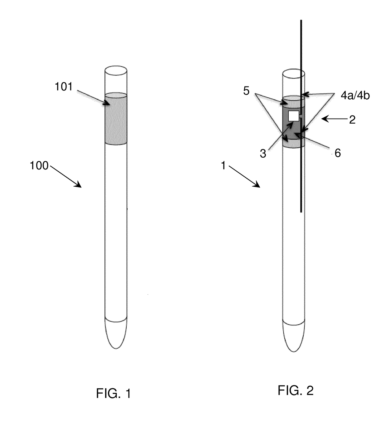
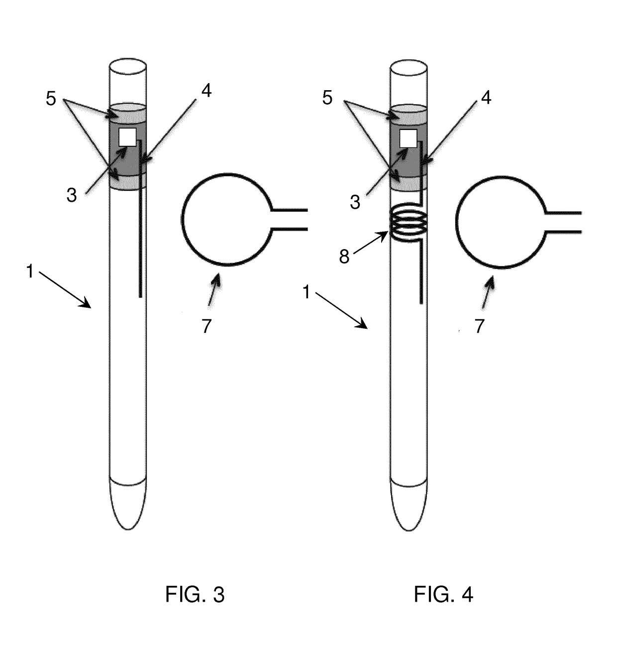
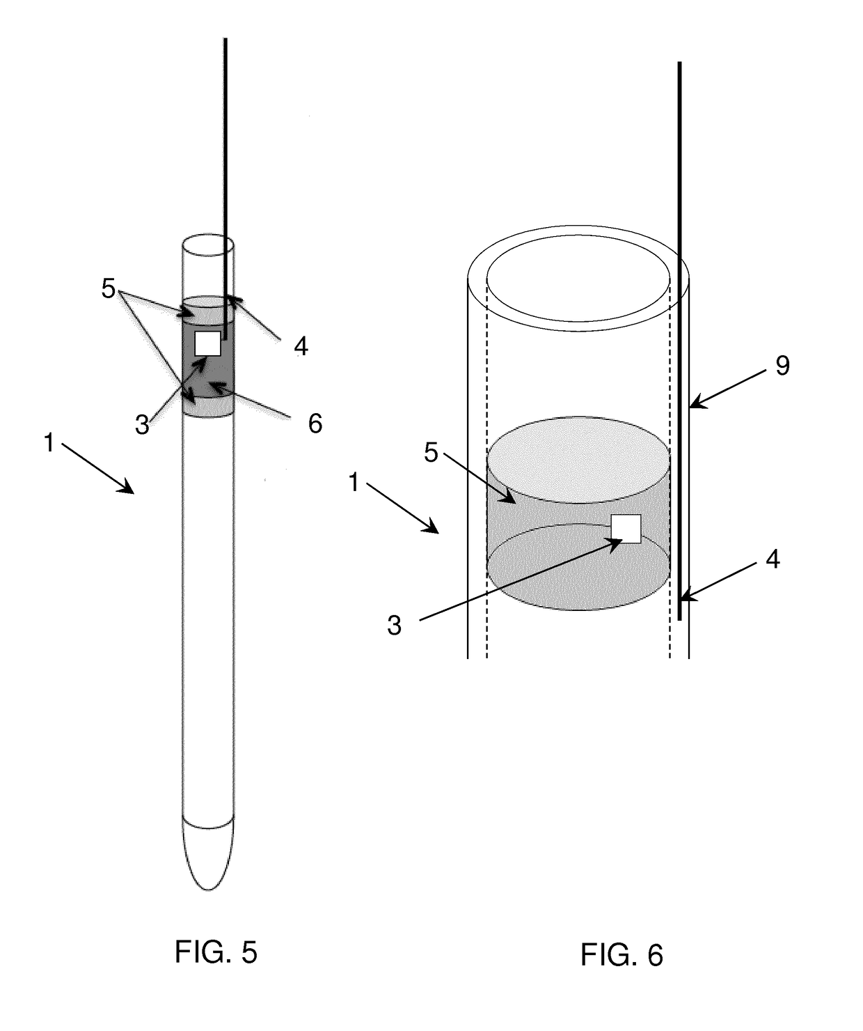
[0024]The present disclosure relates to a radio-frequency identification system for a cryogenic straw comprising:[0025]at least one integrated circuit configured to store information and generate a radio-frequency signal in a frequency range of between 30 MHz and 10 GHz or between 100 MHz and 3 GHz, or between 100 MHz and 1GHz;[0026]at least one antenna comprising a conductive thread, wherein the at least one antenna is configured to be integrated in the cryogenic straw or in a sealing element configured to be placed inside the cryogenic straw.

[0027]By operating in the ultra-high frequency range a very thin antenna can be used, which may be a thin conductive thread, preferably of metal, which may embedded in the straw, or, alternatively, in a sealing element that is placed inside the cryogenic straw. In one embodiment, the at least one integrated circuit and the at least one antenna is / are therefore configured to operate at 300 MHz to 3 GHz, which is also known as the decimetre band...


PUM


Abstract

The present disclosure relates to a radio-frequency identification system for a cryogenic straw comprising: at least one integrated circuit configured to store information and generate a radio-frequency signal in a frequency range of between 30 MHz and 3 GHz; and at least one antenna comprising a conductive thread configured to be integrated, such as molded, into a sidewall of the cryogenic straw. The disclosure further relates to a cryogenic straw comprising at least one antenna, the antenna comprising a conductive thread or rod, wherein the at least one antenna is integrated, such as molded, into a sidewall of the cryogenic straw.

Description

[0001]The present disclosure relates to a radio-frequency identification system for cryogenic straws and a cryogenic straw comprising a radio-frequency identification system.BACKGROUND OF INVENTION[0002]Preserving organic material, such as DNA material and sperm samples, requires very low storing temperatures. This has long been achieved by cryogenic freezing where the organic samples are immersed in liquid nitrogen, which has a boiling temperature of −196° C. Cryonic storage at very cold temperatures increases longevity of cells significantly. The cryogenic temperature range has been defined as from −150° C. to absolute zero −273.15° C., the temperature at which molecular motion comes as close as theoretically possible to ceasing completely. When performing an audit of samples stored at cryogenic temperatures, it is desirable to minimize the time the samples spend outside the cryogenic environment.[0003]The biological samples may be preserved in individual plastic straws or vials, ...

Claims


Application Information

Patent Timeline
Patent Type & Authority Applications(United States)
IPC IPC(8): A01N1/02G06K19/07H01Q1/22A61D19/02B01L3/00
CPCA01N1/0268G06K19/072G06K19/0724H01Q1/2225A61D19/024B01L3/502715B01L2300/022B01L2300/1894G06K19/07B01L2300/0838G06K19/0723H01Q1/40
Inventor PEDERSEN, GERT FROLUNDMIKKELSEN, JAN HVOLGAARD
Owner VIKING GENETICS FMBA
Why Eureka
Try Eureka