Downhole Debris-Collecting Tool Having An Improved Valve

Active Publication Date: 2019-02-21
ALTUS INTERVENTION TECH AS
View PDF5 Cites 0 Cited by
  • Summary
  • Abstract
  • Description
  • Claims
  • Application Information

AI Technical Summary

Benefits of technology

The present invention is related to a downhole tool used in drilling oil wells. The technical effects of the invention include a housing with a tubular shape that allows for a rotatable shaft, a concentric placement of the rotatable shaft and collection chamber, and a seal member that can be conveniently closed. The seal member can be fixed to the rotatable shaft or it can rotate relative to the shaft. The movable part of the downhole tool can be molded or assembled together using the eyelet principle. Additionally, the movable part can be designed as a pivotably mounted or bendable curved flap that matches the characteristics of the rotatable axis and transfers blades.

Problems solved by technology

These materials are collected in a similar manner in the collection chamber, but have a volatile character and will leak out of the system when the debris-collecting tool is pulled up from a horizontal to a vertical well section.
It is very challenging to collect large amounts of debris with electro mechanical equipment.
Such equipment generally has limited torque, because of the fact these tools are supplied via a cable from the surface.
Expressed differently, the amount of electrical power that can be fed through the cable is limited and thereby the amount of available torque is limited.
However, these valves require a lot of force in order to be operated.
They require a lot of force, because the pollution has to be pressed against the valve to open it and then to be pushed beyond the constriction, which the valve actually forms itself.
Thus, large amounts of energy are consumed while pushing the debris through the traditional valve systems.

Method used


Image

  • Downhole Debris-Collecting Tool Having An Improved Valve
  • Downhole Debris-Collecting Tool Having An Improved Valve
  • Downhole Debris-Collecting Tool Having An Improved Valve

Examples


Embodiment Construction

[0053]The invention provides for a downhole tool for collecting debris having a valve, which does hardly need any force to open, while it ensures a good sealing when the tool is removed from a petroleum well. This will be further explained in the detailed description, which follows.

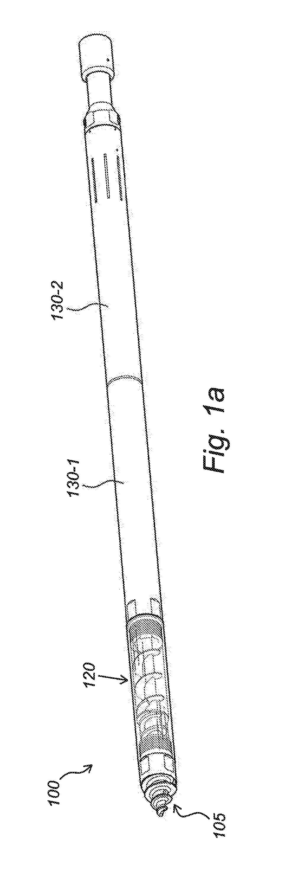
[0054]FIG. 1a shows a downhole tool 100 in accordance with a first embodiment of the invention. The downhole tool 100 comprises a housing 120 with an opening 105 at the tip. In this embodiment the housing 120 forms a valve module 120 of the downhole tool 100, in series with a first collection module 130-1 and a second collection module 130-2, as illustrated. The first collection module 130-1 embodies a first collection chamber, and the second collection module 130-2 embodies a second collection chamber. From now on the collection modules 130-1, 130-2 will be referred to as “collection chambers”. The second collection module 130-2 may comprise a filter section as in this embodiment. In operational use of t...


PUM


Abstract

The downhole tool comprises: (i) a housing connected with a collection chamber for receiving debris, the housing having an opening for collecting the debris from the petroleum well, the opening in fluid communication with the collection chamber through the housing; (ii) a rotatable shaft with transport blades arranged within the housing and extending from the opening to the collection chamber, the rotatable shaft configured for transporting debris from the opening to the collection chamber in operational use; (iii) an annular area defined between the rotatable shaft and an inner wall of the housing and (iv) a valve configured for keeping debris in the collection chamber. The valve is located within the housing between the opening and the collection chamber. The valve comprises a seal member with a movable part mounted in the annular area and around the rotatable shaft. The valve is opened when the movable part moves in direction of the collection chamber and is configured such that the movable part of the seal member is only movable in the direction towards the collection chamber when closed. The downhole tool provides a valve, which is easily opened, requiring a very small force, while providing a very good sealing effect when the seal member is closed.

Description

FIELD OF THE INVENTION[0001]The invention relates to a downhole tool for collecting debris in a petroleum well. The invention further relates to a seal member for use in such tool.BACKGROUND OF THE INVENTION[0002]Debris-collecting tools of the kind of the invention are generally used in a casing or tubing in a well. Such tools typically comprise an electric engine-based collection system. An example of such tool typically comprises transport blades on a rotatable shaft, which extends through a collection chamber, a filter section for particle separation, a front part with an input screw and valve. Such downhole tool is known from patent publication WO03 / 036020A1.[0003]Pollution in a petroleum well typically consists of different materials and often matter with a binding effect. Such material typically collects in the collection chamber and does not fall out even if the debris-collecting tool is pulled out of the well. The collected material must in such cases be scraped out or washe...

Claims


Application Information

Patent Timeline
IPC IPC(8): E21B27/04E21B34/06
CPCE21B27/04E21B34/06E21B27/00E21B37/00E21B11/04E21B31/08
Inventor HAUGLAND, LASSEOSALAND, ESPEN
Owner ALTUS INTERVENTION TECH AS
Why Eureka
Try Eureka