Device for conveying material during track laying

Inactive Publication Date: 2016-02-25
SYST 7 RAILSUPPORT
View PDF3 Cites 7 Cited by
  • Summary
  • Abstract
  • Description
  • Claims
  • Application Information

AI Technical Summary

Benefits of technology

[0006]The invention is thus based on the object of providing a device of the kind mentioned above which avoids the aforementioned disadvantages, i.e. especially offers an increased useful volume per material-

Problems solved by technology

The disadvantages of this configuration are the unused space beneath the oblique inclination or elevation and the required increased drive force for the conveyor belt, which is necessary in order to convey the conveying material up the inclination.
It is also disadvantageous in the current configurations that a relatively large empty space is produced in the region of the transfer conveyor belt between the individual coupled material-conveying silo units.
This leads to relatively high dead weights and reduced loading volumes that can be used.
This means simultaneously that a relatively large number of axles are required per useful loading weight.
If the trains composed of the material-conveying silo

Method used


Image

  • Device for conveying material during track laying
  • Device for conveying material during track laying
  • Device for conveying material during track laying

Examples


Embodiment Construction

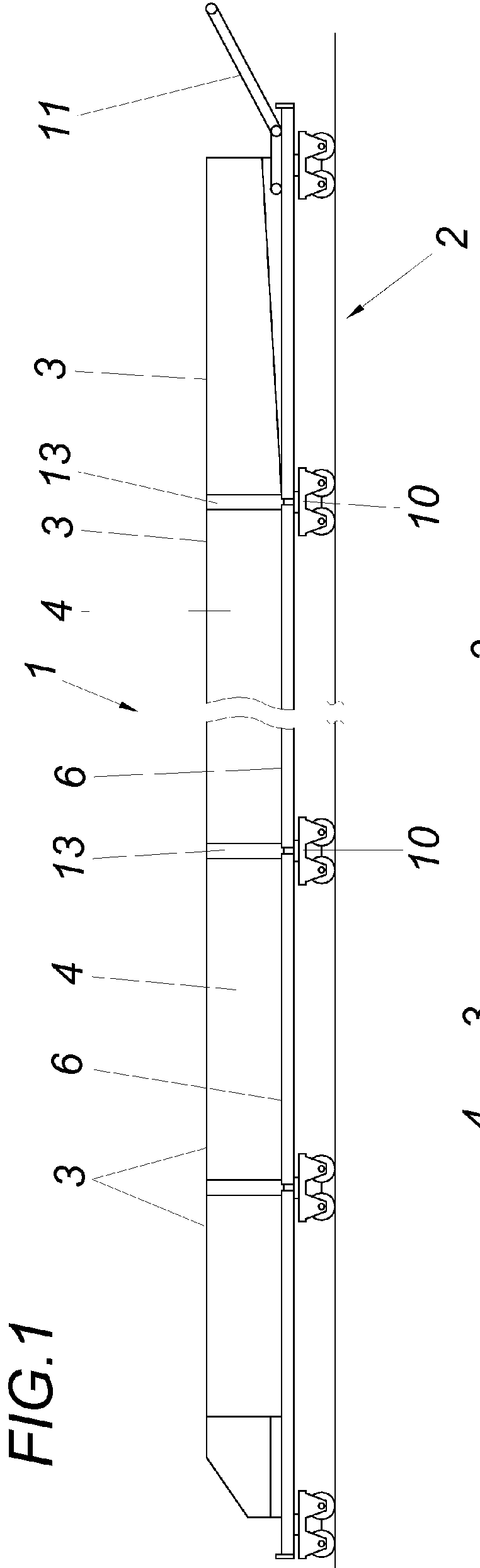
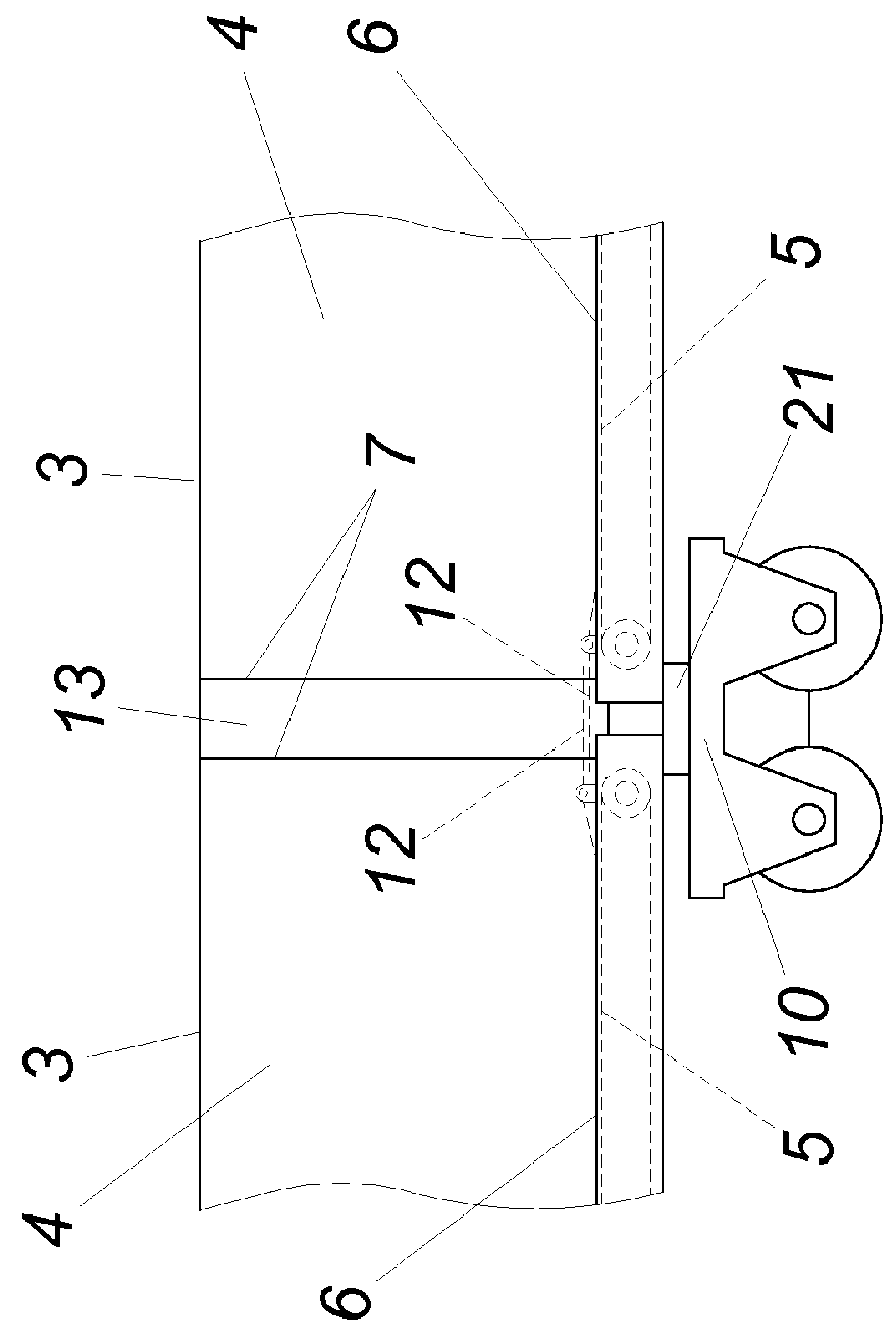
[0025]The illustrated device for conveying material in tracklaying, i.e. a material-conveying silo 1, comprises material-conveying silo units 3 which can be moved on a track 2 and which receive material between side walls 4 defining the silo chamber on a bottom conveyor belt 5 for conveying the material along the bottom 6, wherein a material-conveying silo 1 comprises several material-conveying silo units 3 which are coupled to each other and which, in the region of their mutually facing face ends 7, comprise devices for transferring the material from a material-conveying silo unit 3 to the next material-conveying silo unit 3.

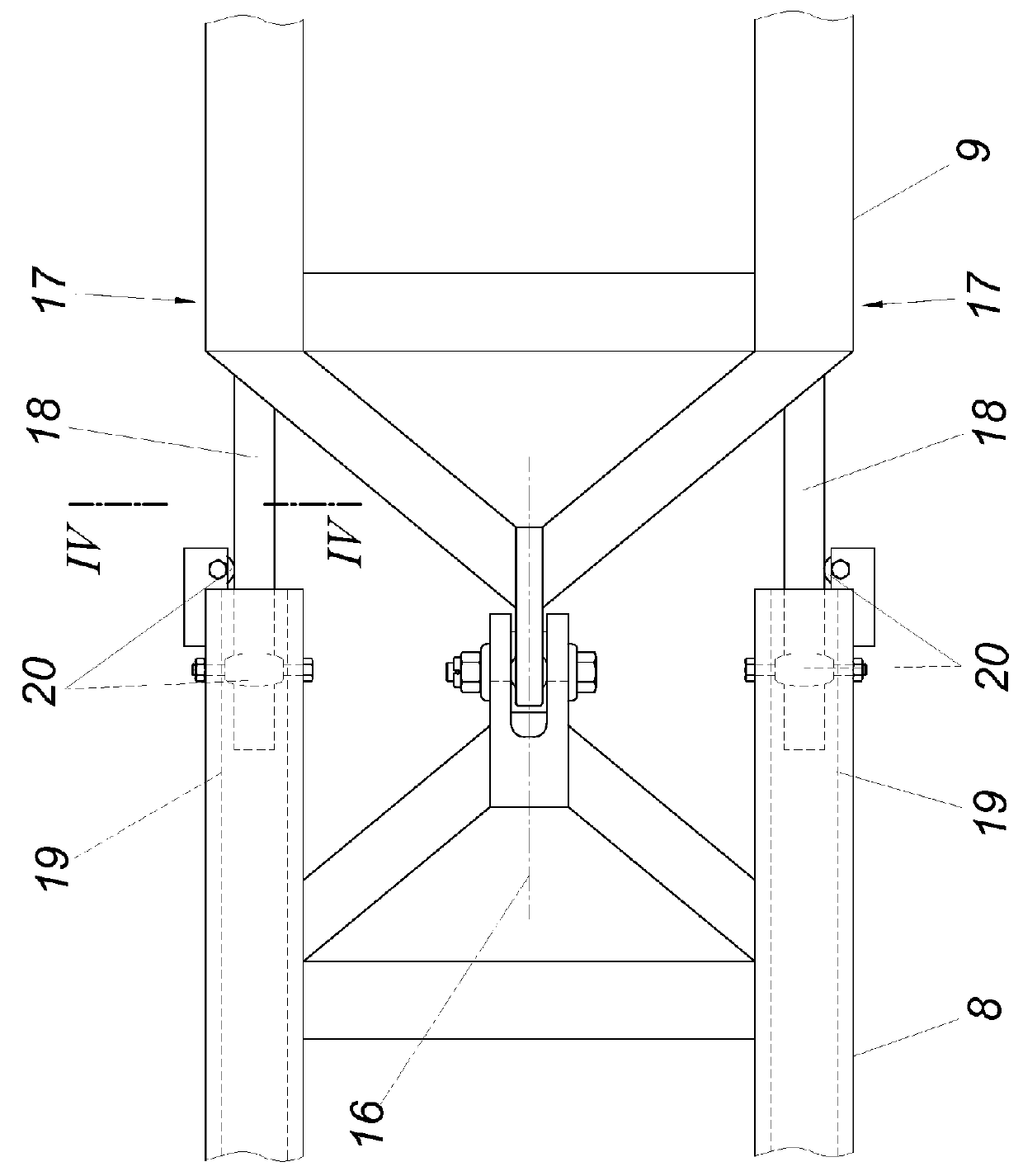
[0026]The material-conveying silo 1 is arranged in articulated configuration for the purpose of utilising in the best possible way the theoretically available total silo volume, wherein the frames 8, 9 of two mutually adjoining material-conveying silo units 3 rest in an articulated manner on a common running gear 10 and the silo chamber is continuously arranged...


PUM

PropertyMeasurementUnit
Volumeaaaaaaaaaa
Frictionaaaaaaaaaa

Abstract

A device, proposed for conveying material during track laying, includes material-conveying silo units which can be moved on a track and receive material between side walls which define the silo chamber on a bottom conveyor belt for conveying the material along the bottom. A material-conveying silo includes a plurality of material silo units which are coupled to one another and, in the region of their end faces which face one another, include devices for transferring the material from one material-conveying silo unit to the next material-conveying silo unit. In order to increase the useful volume of the material-conveying silo, the material-conveying silo is of articulated configuration, where the frames of two material-conveying silo units which adjoin one another are supported in an articulated manner on a common running gear, and the silo chamber is of continuous configuration.

Description

FIELD OF THE INVENTION[0001]The invention relates to a device for conveying material during track laying, comprising material-conveying silo units which can be moved on a track and receive material between side walls which define the silo chamber on a bottom conveyor belt for conveying the material along the bottom, wherein a material-conveying silo comprises a plurality of material silo units which are coupled to one another and, in the region of their end faces which face one another, comprise devices for transferring the material from one silo unit to the next silo unit.DESCRIPTION OF THE PRIOR ART[0002]Material-conveying silo units for loading, supplying and conveying track-laying material such as ballast, excavated material or subgrade protection layer material etc are used in track laying and track maintenance. The material-conveying silo units are used in construction and reconditioning measures for railway tracks. They convey and store either new materials such as ballast or...

Claims


Application Information

Patent Timeline
IPC IPC(8): B61D47/00B61D3/16B65G15/00B65G67/02
CPCB61D47/00B65G67/02B65G15/00B61D3/16B61D15/00E01B27/02C07K16/243E01B27/00C07K2317/76C07K2317/92
Inventor LICHTBERGER, BERNHARD
Owner SYST 7 RAILSUPPORT
Why Eureka
Try Eureka