
Bouncing Ornament
a technology of ornaments and balls, applied in the field of balls, can solve the problems of not adding all of the energy of the push, inefficient energy use, and all of the momentum
- Summary
- Abstract
- Description
- Claims
- Application Information
AI Technical Summary
Benefits of technology
Problems solved by technology
Method used
Image

Examples
Embodiment Construction
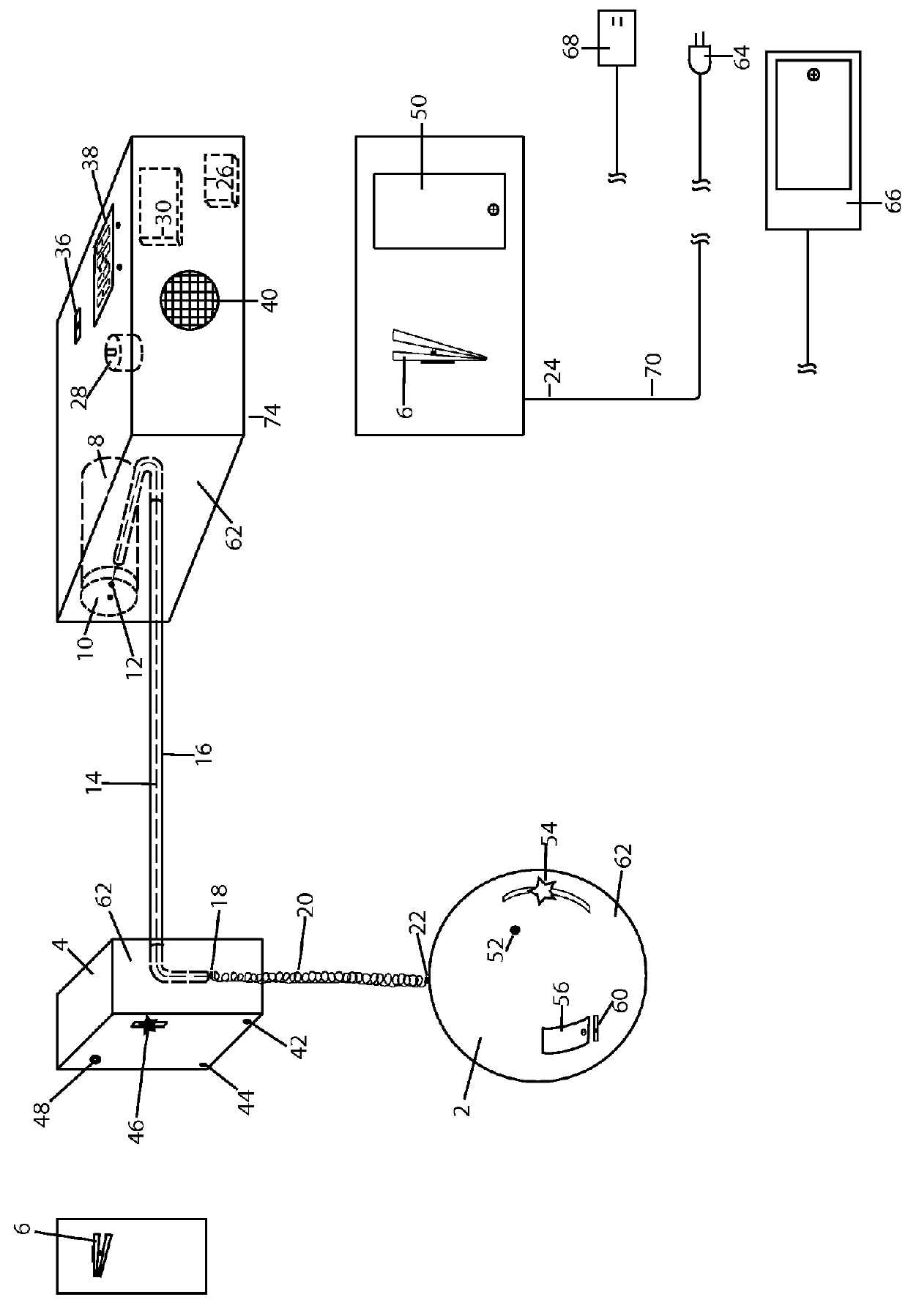
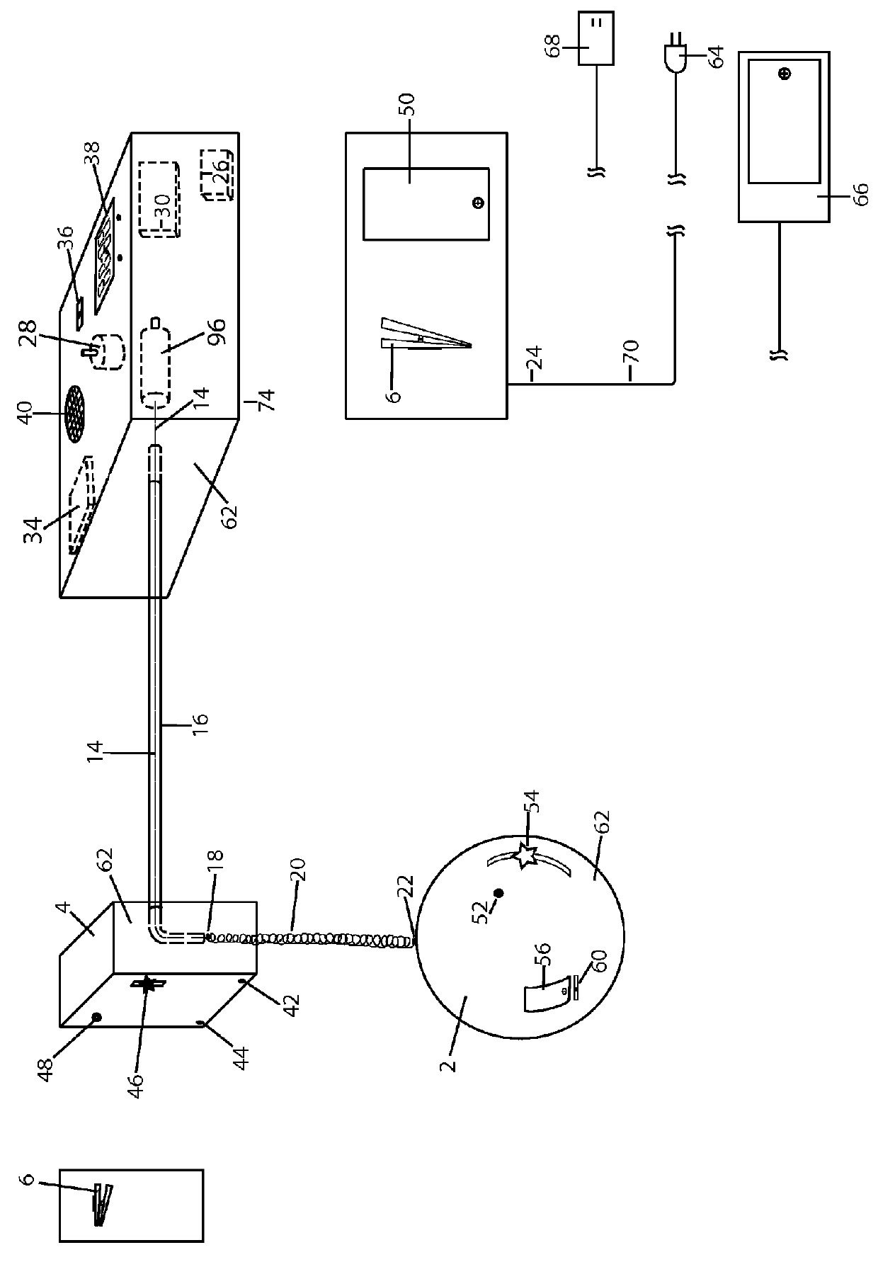
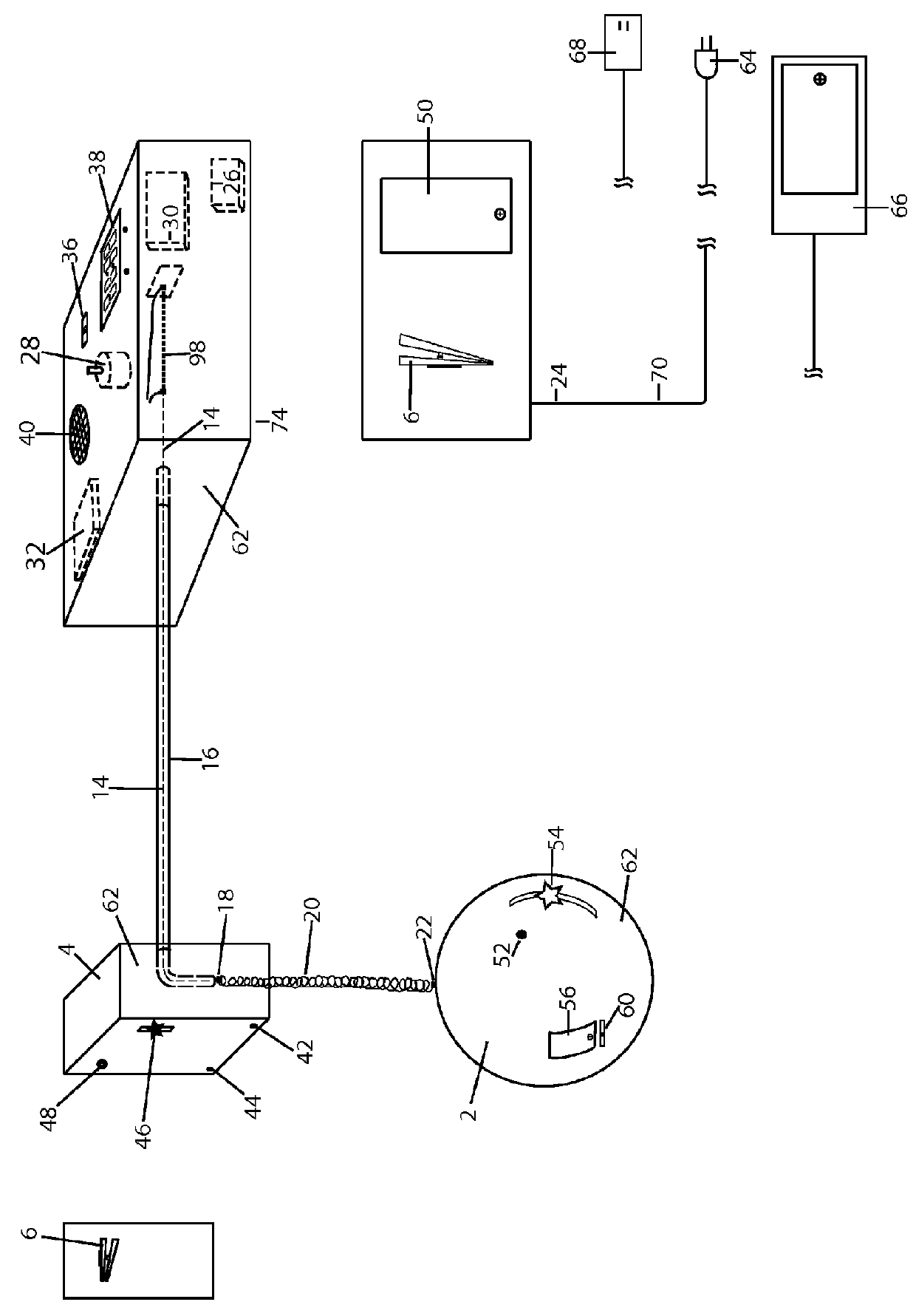
[0018]Referring to FIG. 1, a remote motor driven bouncing ornament includes; an ornament 2, an ornament upper housing 4, in this embodiment it can be for a decorative purpose and also to hold any other miscellaneous lights 48, photovoltaic sensor 44, motion sensor 42, motion device 46. The ornament 2, is attached to the spring 20, with the ornament to spring connector 22. The spring 20, at the top connects to the a transmission mechanism 14, in this case a line made of thread, by means of a spring to transmission connector 18, that connector in this embodiment is a clip attached to the transmission mechanism 14. The transmission mechanism 14, is supported and rides in the transmission conduit 16, that terminates in the upper housing 4. The transmission conduit 16, on the remote motor housing 74, side terminates in front of the rotor 10, where the transmission mechanism 14 connects to the transmission attachment swivel mechanism 12, this is to allow the rotation of the motor to be co...
PUM
 Abstract
Description
Claims
Application Information