Bouncing ornament

a technology of ornaments and balls, applied in the field of balls, can solve the problems of not adding all of the energy of the push, inefficient energy use, and all of the momentum

Active Publication Date: 2018-02-27
COLEMAN SHAWN
View PDF5 Cites 0 Cited by
  • Summary
  • Abstract
  • Description
  • Claims
  • Application Information

AI Technical Summary

Benefits of technology

[0003]According to one preferred embodiment of the current invention, a bouncing ornament may comprise: at least one ornament but can be up ten ornaments that connects to an upper housing by a tether, spring and bungee. The upper housing can connect to a remote motor housing by a transmission conduit. By using a remote motor housing the weigh, size and bulk of the motor and other mechanisms are moved from the upper housing to the remote motor housing. In one preferred embodiment the desired location can be the tip of a Christmas tree branch which could bend due to the weight of the components. By using a remote motor housing the weight, size and bulk of the components can be moved further along the branch towards the trunk of the tree. In a second preferred embodiment of the current invention: the ornament itself can connect directly to the remote motor housing to eliminate the upper housing.
[0004]The Bouncing Ornament FIG. 1 through FIG. 9 may be made with any material. The configuration needs to be such that the ornament hangs freely so it can bounce up and down when powered on. It can do this by taking advantage of the ornaments “natural frequency”. This can be explained by Hook's Law which will determine the period (the number of bounces per second) of the ornament on the tether, spring and bungee, from this point forward also know as the spring. Spring stiffness can be used to control the level of dampening by increasing the thickness or decreasing thickness of the spring. By adding a “Periodic Driving Force” (a motor or a solenoid) configured to generate a periodic push or pull depending on the application also know as the pulse of force (a device that gives a small push periodically like someone pushing a swing). This will cause the ornament to develop and maintain a periodic motion also known as a “Simple Harmonic Motion”.
[0005]In order to keep the ornament moving requires the addition of more energy or force. This can be accomplished by pulling up and pushing down (releasing to gravity) the spring with the ornament attached. Please note the length of the throw can be very small at least 1 mm and up to approximately 50 mm but preferably between 10 mm and 25 mm and can vary according to the need of the design and to accommodate the weight of the ornament. A very small push can add energy efficiently if it happens at the instant when the ornament has moved to its highest position and begins to move back to the point of stable equilibrium. If the push occurs a little late then not all of the energy of the push is added (inefficient use of energy). Still worse is if the push occurs too soon, when this happens the result will be to counter act some or all of the momentum, slowing it down or stopping it altogether. The goal is to add a small amount of energy to the cycle to compensate for the energy lost due to friction. By adding energy correctly it will keep the ornament bouncing smoothly and at a uniform rate with very little input of power. This is know as resonance which occurs when the rhythm of the energy source matches the natural characteristic frequency of the oscillation, otherwise called the resonant frequency. Please note it is common to call the source of energy the driving force.

Problems solved by technology

If the push occurs a little late then not all of the energy of the push is added (inefficient use of energy).
Still worse is if the push occurs too soon, when this happens the result will be to counter act some or all of the momentum, slowing it down or stopping it altogether.
Another issue is that the ornament can sometimes vary in weight due to the amount of moisture in the environment or other factors.

Method used


Image

  • Bouncing ornament
  • Bouncing ornament
  • Bouncing ornament

Examples


Embodiment Construction

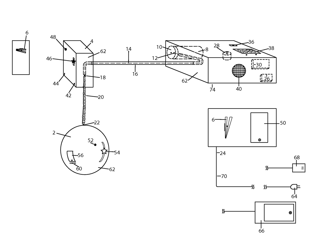
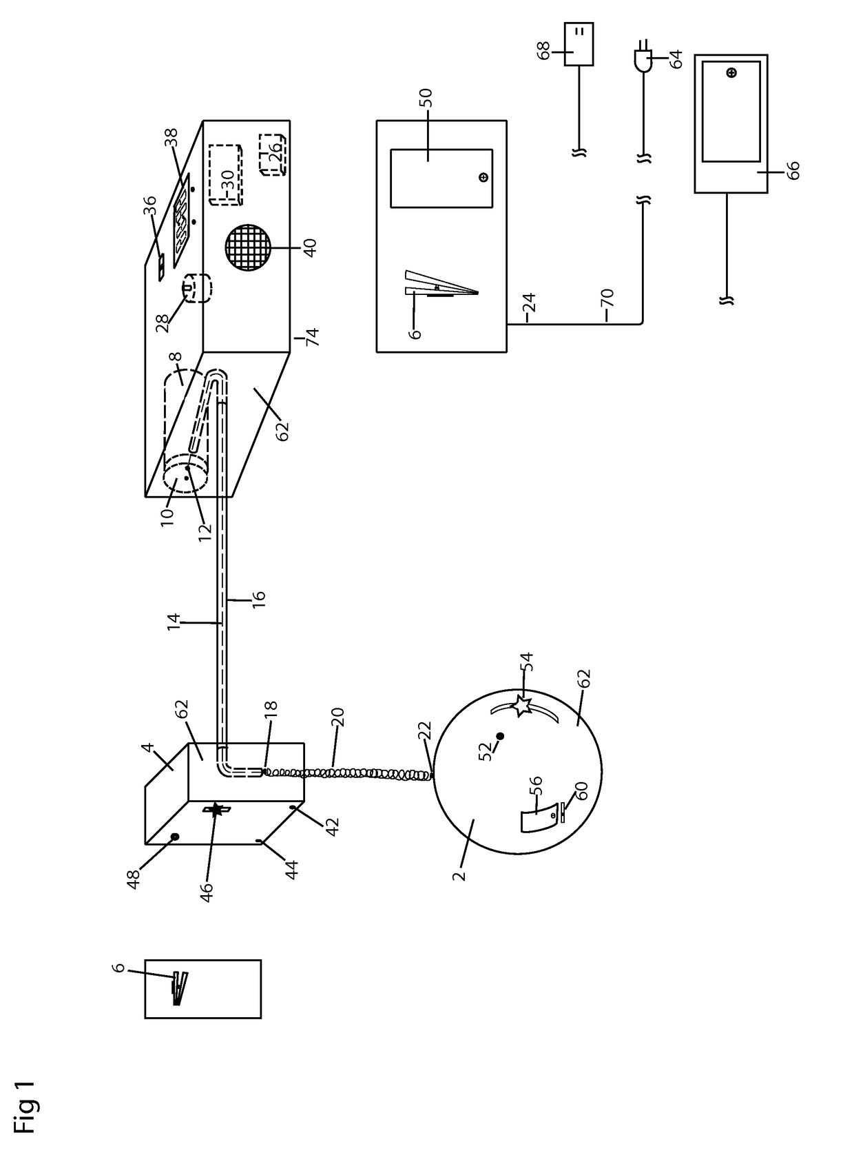
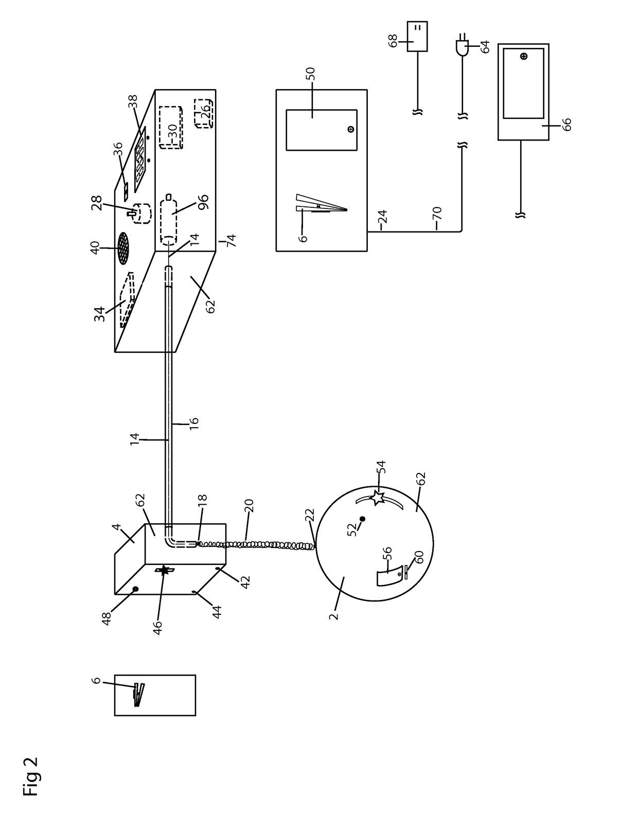
[0018]Referring to FIGS. 1 through 8, the present invention includes a bouncing ornament. The bouncing ornament includes a rotor 10 having a front surface and an outer edge forming the circumference of the rotor 10. A motor 8 rotates the rotor 10. The present invention further includes an upper housing 4. A transmission mechanism 14, such as a tether, runs through the upper housing 4. The tether includes a first end and a second end. A swivel 12 connects the first end of the tether to the front surface of the rotor 10. The swivel 12 is connected to the rotor off center of the front surface in between a longitudinal axis of the rotor 10 and the outer edge of the rotor 10. An ornament 2 is attached to the second end of the tether and is disposed below the upper housing 4. A same directional circular motion of the rotor 10 pulls the ornament 2 upward and releases the ornament 2 downward.

[0019]Referring to FIG. 1, a remote motor driven bouncing ornament includes; an ornament 2, an ornam...


PUM


Abstract

A bouncing ornament that includes housings a motor, a transmission mechanism and a transmission conduit The transmission mechanism transfers the motion of the motor to the ornament via a spring which causes the ornament to bounce up and down.

Description

RELATED APPLICATION[0001]This application claims priority to U.S. Provisional Patent Application No. 61 / 853,623, Filing Date Apr. 9, 2013, Entitled Luminescent Ornament.BACKGROUND[0002]An ornament that connects by a tether, spring, and bungee to a housing that rests, hangs, mounts, and sits at its desired display location. The housing holds a motor that provides the up and down motion to the tether, spring, and bungee causing the ornament to bounce up and down. This adds a unique motion to the ornament that current ornament designs don't have.SUMMARY OF THE INVENTION[0003]According to one preferred embodiment of the current invention, a bouncing ornament may comprise: at least one ornament but can be up ten ornaments that connects to an upper housing by a tether, spring and bungee. The upper housing can connect to a remote motor housing by a transmission conduit. By using a remote motor housing the weigh, size and bulk of the motor and other mechanisms are moved from the upper housi...

Claims


Application Information

Patent Timeline
Patent Type & Authority Patents(United States)
IPC IPC(8): E04G3/00A47G33/08
CPCA47G33/0809
Inventor COLEMAN, SHAWN
Owner COLEMAN SHAWN
Why Eureka
Try Eureka