Vehicle lighting unit having bulb fixation structure

a technology for fixing structures and lighting fixtures, which is applied in the direction of fixed installation, transportation and packaging, and light and heating equipment, etc. it can solve the problems of insufficient fixation of bulbs and the tendency of the support spring 4 to float, so as to facilitate the engagement of the engagement claws and prevent the loosening of bulbs

Active Publication Date: 2016-02-25
STANLEY ELECTRIC CO LTD
View PDF7 Cites 2 Cited by
  • Summary
  • Abstract
  • Description
  • Claims
  • Application Information

AI Technical Summary

Benefits of technology

[0011]The presently disclosed subject matter was devised in view of these and other problems and features in association with the conventional art. According to an aspect of the presently disclosed subject matter, a fixation structure for a vehicle lighting unit can fix a bulb with reliability.
[0017]In the first aspect of the presently disclosed subject matter, the use of the countersunk screws for attachment of the supporter spring can prevent the interference between the screws and the bulb, thereby eliminating the limit of the number of the usable screws. Therefore, the supporter spring can be fixed at three or more locations with the three or more countersunk screws in the circumferential direction of the supporter spring to the holder of the main body reliably, meaning that the floating of the supporter spring can be reliably prevented. The reliable fixation of the supporter spring can ensure the simultaneous passing of the plurality of engagement claws of the bulb through the plurality of claw escape holes of the supporter spring as well as the engagement of the bulb with the engagement springs of the supporter spring, to thereby always reliably fix the bulb to the main body of the lighting unit without wrong assembling.
[0019]In the third aspect of the presently disclosed subject matter, the assembled bulb to the main body can be in contact with the stopper rib projected from the main body to be prevented from rotating. This can prevent the loosening of the bulb.
[0020]In the fourth aspect of the presently disclosed subject matter, the supporter spring can have the projections projected from one circumferential ends of the respective claw escape holes of the supporter spring. The circumferential end herein means the side where the engagement claw starts to engage with the lower surface of the supporter spring when the bulb is rotating. Therefore, even if all the engagement claws do not pass through the corresponding claw escape holes simultaneously so that part of the engagement claw does not pass through the claw escape hole and tries to stride over the supporter spring, the projection for preventing wrong assembling can prevent the engagement claw from striding over the supporter ring. Therefore, all the engagement claws of the bulb can simultaneously pass through the claw escape holes of the supporter spring to reliably engage with the engagement springs of the supporter spring, to thereby always reliably fix the bulb to the main body of the lighting unit without wrong assembling.
[0021]In the fifth aspect of the presently disclosed subject matter, the engagement springs can be formed on a side of the holder and the projections can be formed on a side opposite to the side of the holder with respect to the supporter spring. In this case, the engagement springs and the projections can be formed continuously on the holder side and on the opposite side thereto, respectively. This configuration can facilitate the engagement of the engagement claws of the bulb with the engagement springs by the projections (on the side opposite to the holder side) that can prevent the engagement claws from striding over the supporter spring on that side and guide the engagement claws at their rear surfaces toward the engagement springs on the holder side.

Problems solved by technology

The problem is such that the supporter spring 4 tends to float when it is fixed only by two screws 5.
This results in insufficient fixation of the bulb 6 to the reflector 1 due to wrong assembling.

Method used


Image

  • Vehicle lighting unit having bulb fixation structure
  • Vehicle lighting unit having bulb fixation structure
  • Vehicle lighting unit having bulb fixation structure

Examples


Embodiment Construction

[0030]A description will now be made below to a vehicle lighting unit of the presently disclosed subject matter with reference to the accompanying drawings in accordance with exemplary embodiments.

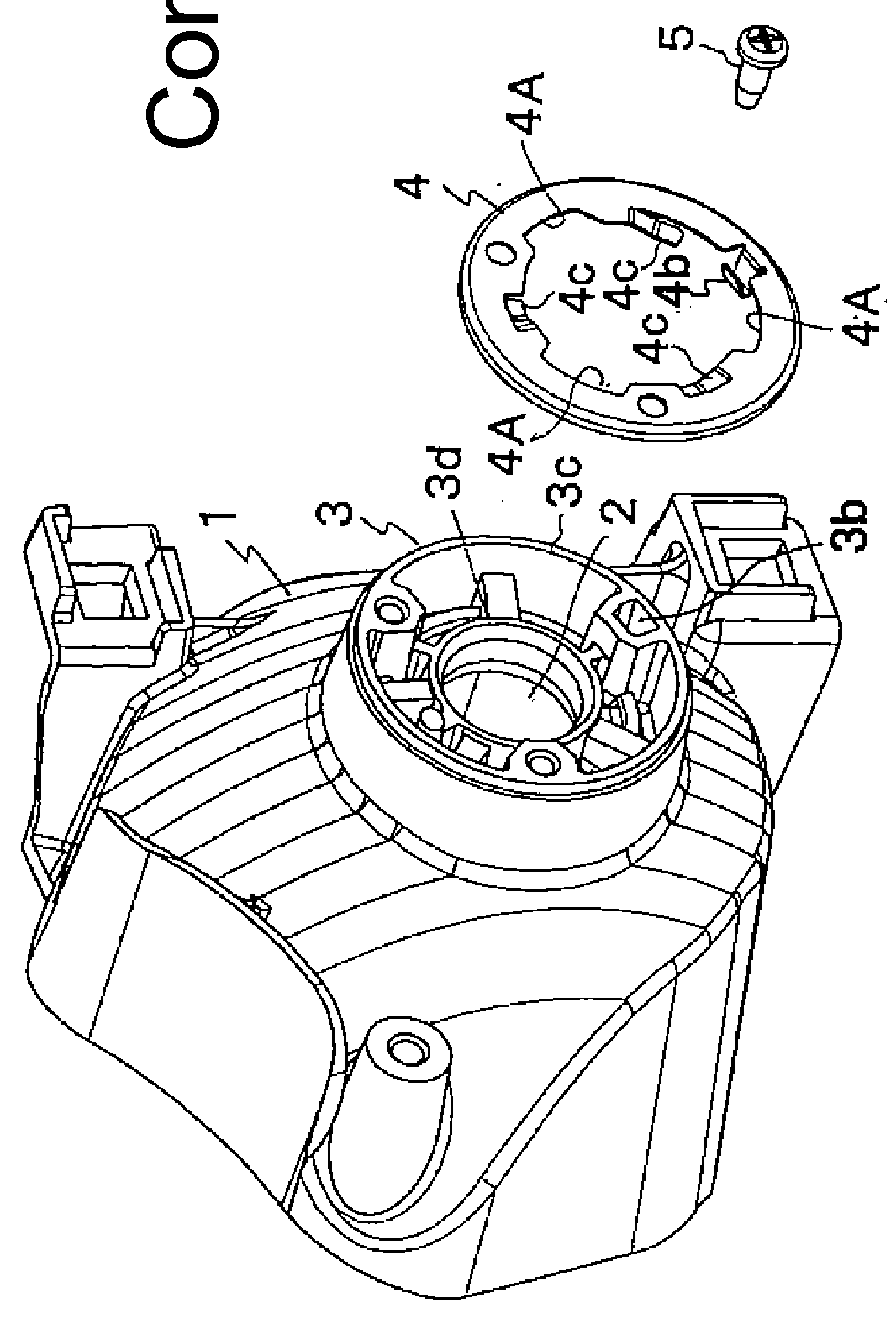
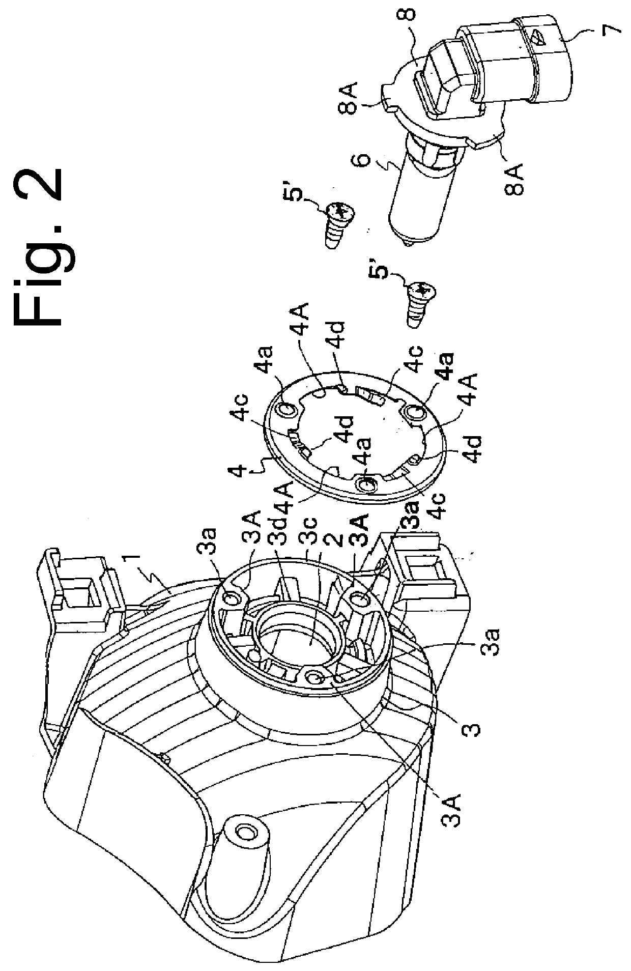
[0031]FIG. 2 is an exploded perspective view of a vehicle lighting unit having a bulb fixation structure for fixing a bulb, made in accordance with the principles of the presently disclosed subject matter. FIG. 3 is a perspective view illustrating a state before the bulb is fixed to the main body of the vehicle lighting unit with the bulb fixation structure. FIG. 4 is a front view of a holder of a reflector, and FIG. 5 is a cross sectional view taken along line A-A in FIG. 4. FIG. 6 is a front view of a supporter spring, and FIG. 7 is a cross sectional view taken along line B-B in FIG. 6. In these drawings, the same or similar components as or to those illustrated in FIG. 1 are denoted by the same reference numerals as those in FIG. 1.

[0032]As illustrated in FIG. 2, the vehicle lighting un...


PUM


Abstract

A vehicle lighting unit with a bulb fixation structure is configured such that a metal supporter spring is attached to an opening end face of a holder projected from a peripheral edge of a bulb attachment hole opened in a reflector, engagement claws provided to the bulb pass through respective claw escape holes formed in the supporter spring so that the bulb is incorporated within the holder, and then the bulb is rotated. Thereby, the bulb is fixed to the main body with a type of a bayonet scheme in which the engagement claws of the bulb are interposed in between and held by the engagement spring of the supporter spring and an opening end face of the bulb attachment hole. The supporter spring is attached to the opening end face of the holder by countersunk screws at at least three locations in a circumferential direction of the supporter spring.

Description

[0001]This application claims the priority benefit under 35 U.S.C. §119 of Japanese Patent Application No. 2014-169494 filed on Aug. 22, 2014, which is hereby incorporated in its entirety by reference.TECHNICAL FIELD[0002]The presently disclosed subject matter relates to a vehicle lighting unit having a bulb fixation structure for fixing a bulb to a reflector or the like member with a bayonet mechanism.BACKGROUND ART[0003]Conventional vehicle lighting units have employed bulbs as a light source and examples of such bulbs may include HB3 type, HB4 type, HIR2 type, etc. Such a bulb can be detachably fixed to the main body of a vehicle lighting unit, such as to a reflector, a housing, or the like with a bayonet mechanism. Examples of this type of vehicle lighting unit may include those described in Japanese Patent Application Laid-Open No. Hei. 10-031901 and Japanese Patent No. 2978795.[0004]A description will now be given of one example of a fixation structure for fixing a bulb by mea...

Claims


Application Information

Patent Timeline
Patent Type & Authority Applications(United States)
IPC IPC(8): F21S8/10
CPCF21S48/1113F21S48/1109F21S41/162F21S41/194F21S41/19
Inventor TOYOYAMA, HIDEKIKOBAYASHI, YASUHIRO
Owner STANLEY ELECTRIC CO LTD
Why Eureka
Try Eureka