

Robot apparatus and method for controlling robot apparatus
a robot and robot technology, applied in the field of robot apparatus, can solve the problems of inability to complete the coordinate positioning comparison in time, inability to stabilize the positioning accuracy, and inability to complete the coordinate positioning comparison
- Summary
- Abstract
- Description
- Claims
- Application Information
AI Technical Summary
Benefits of technology
Problems solved by technology
Method used
Image

Examples
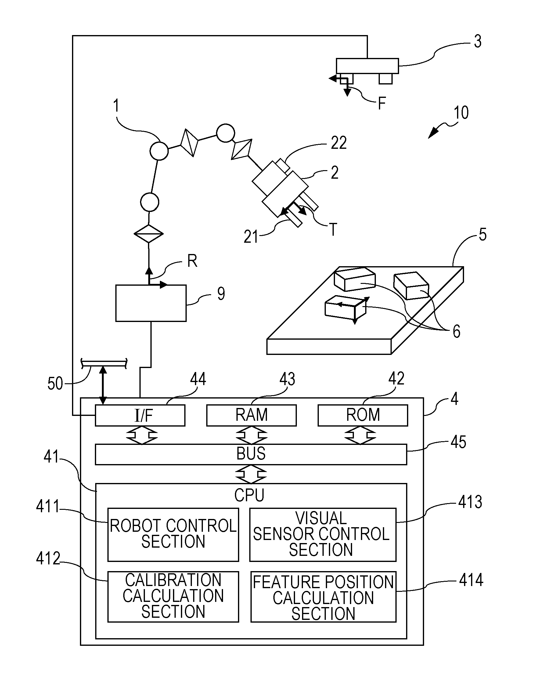
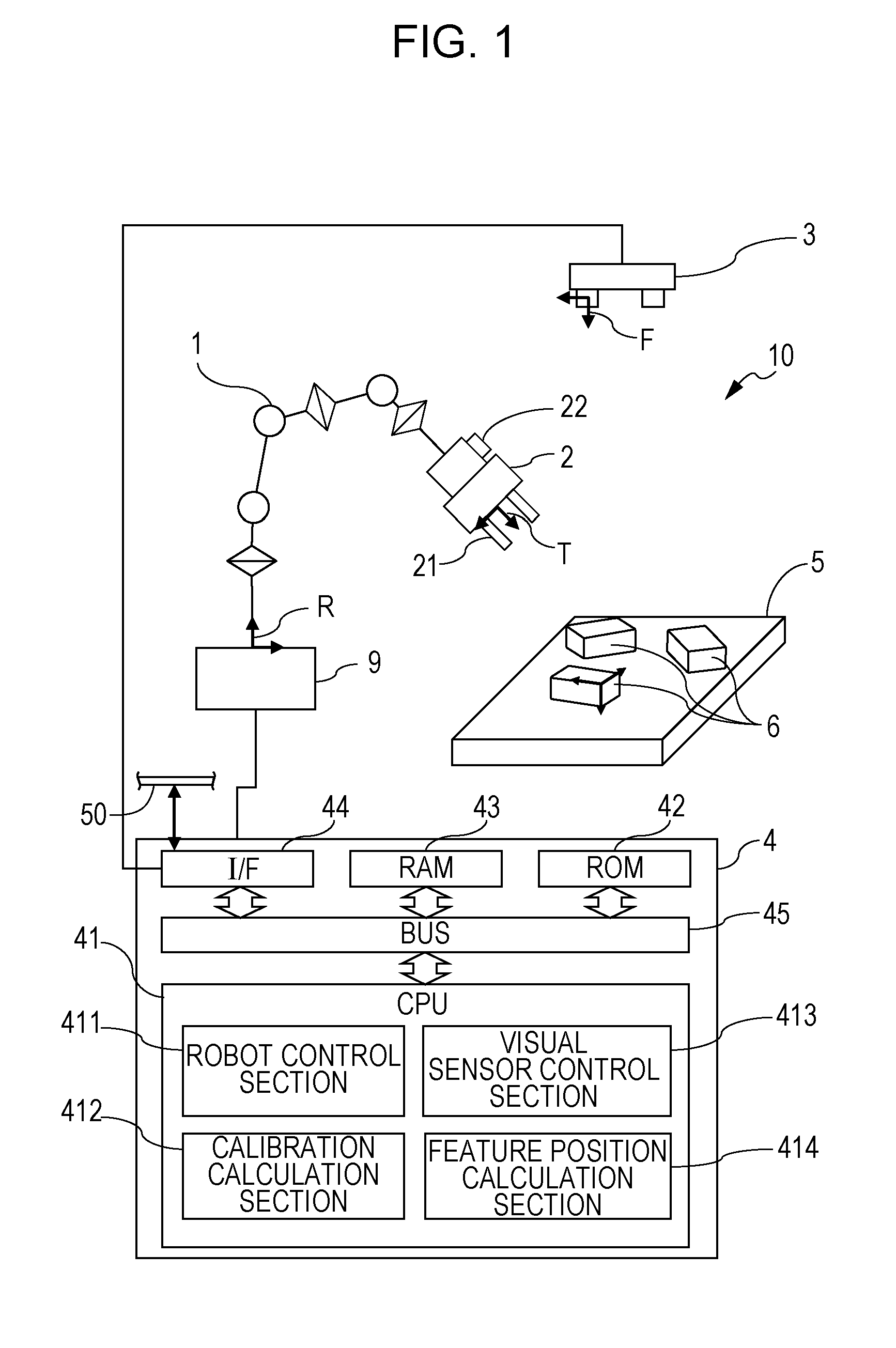
first embodiment
[0030]First, numerical expressions herein will be described. The following numerical expressions apply not only to a first embodiment but also to other embodiments.
Definitions of Numerical Expressions Herein
[0031]In the following description, three-dimensional coordinate systems will be used for representing six-degree-of-freedom positions and orientations of each component, and a position and an orientation in a certain coordinate system relative to another coordinate system will be represented by a coordinate transformation matrix (homogeneous transformation matrix). A coordinate transformation matrix indicating a position and an orientation in a certain coordinate system B relative to a certain coordinate system A will be denoted by AHB. The relative position and orientation indicated by the coordinate transformation matrix will also be referred to simply as a “relative position and orientation AHB”. AHB denotes a 4×4 homogeneous transformation matrix and is defined as follows us...
second embodiment
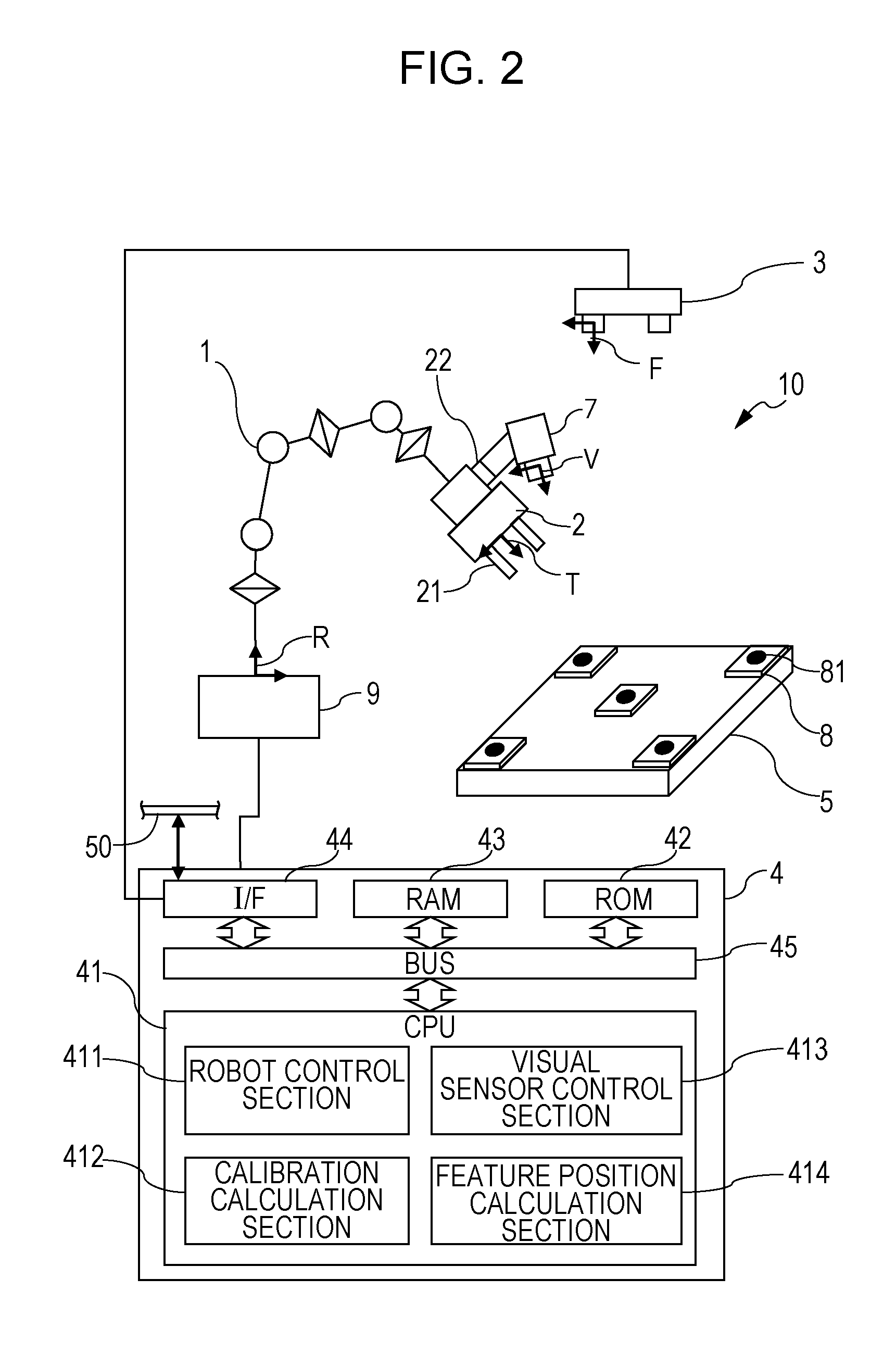
[0094]Next, the system configuration of a robot system 10a according to a second embodiment of the present embodiment during calibration will be described with reference to FIG. 7. In the second embodiment, the amount of work performed by the operator to prepare for calibration can be reduced compared to in the first embodiment.
[0095]The robot system 10a according to the second embodiment is different from the robot system 10 according to the first embodiment in the following three points.
[0096]First, a hand camera 7a that can be held by the robot hand 2 is provided as a hand visual sensor instead of the hand camera 7, and a hand camera rest 71a is provided.
[0097]Second, reference members detected by the fixed camera 3 and the hand camera 7a during calibration are markers 8a that can be arbitrarily arranged by the operator.
[0098]Third, a calibration position and orientation calculation section 415 that calculates calibration positions and orientations of the markers 8a arbitrarily a...
third embodiment
[0128]Next, a third embodiment of the present invention will be described. In the first and second embodiments, the fixed visual sensor is the fixed camera 3 and the hand visual sensor is the hand camera 7 or 7a, that is, the fixed visual sensor and the hand visual sensor are two separate independent cameras. On the other hand, in the third embodiment, a fixed visual sensor (stereo camera 3b) can be removed from an original position thereof and mounted on the robot hand 2 at the end of the robot arm 1. The fixed visual sensor is then temporarily used as a hand visual sensor. In other words, the stereo camera 3b doubles as the fixed visual sensor and the hand visual sensor. The present embodiment will be described hereinafter while emphasizing differences from the first and second embodiments.
[0129]FIGS. 10A and 10B illustrate the configuration of a robot system 10b according to the third embodiment and a relationship between coordinate systems, coordinates, and coordinate transforma...
PUM
 Abstract
Description
Claims
Application Information