
Ultrasonic liquid level sensing systems

Active Publication Date: 2016-03-03
VERSUM MATERIALS US LLC
View PDF5 Cites 2 Cited by
  • Summary
  • Abstract
  • Description
  • Claims
  • Application Information

AI Technical Summary

Benefits of technology

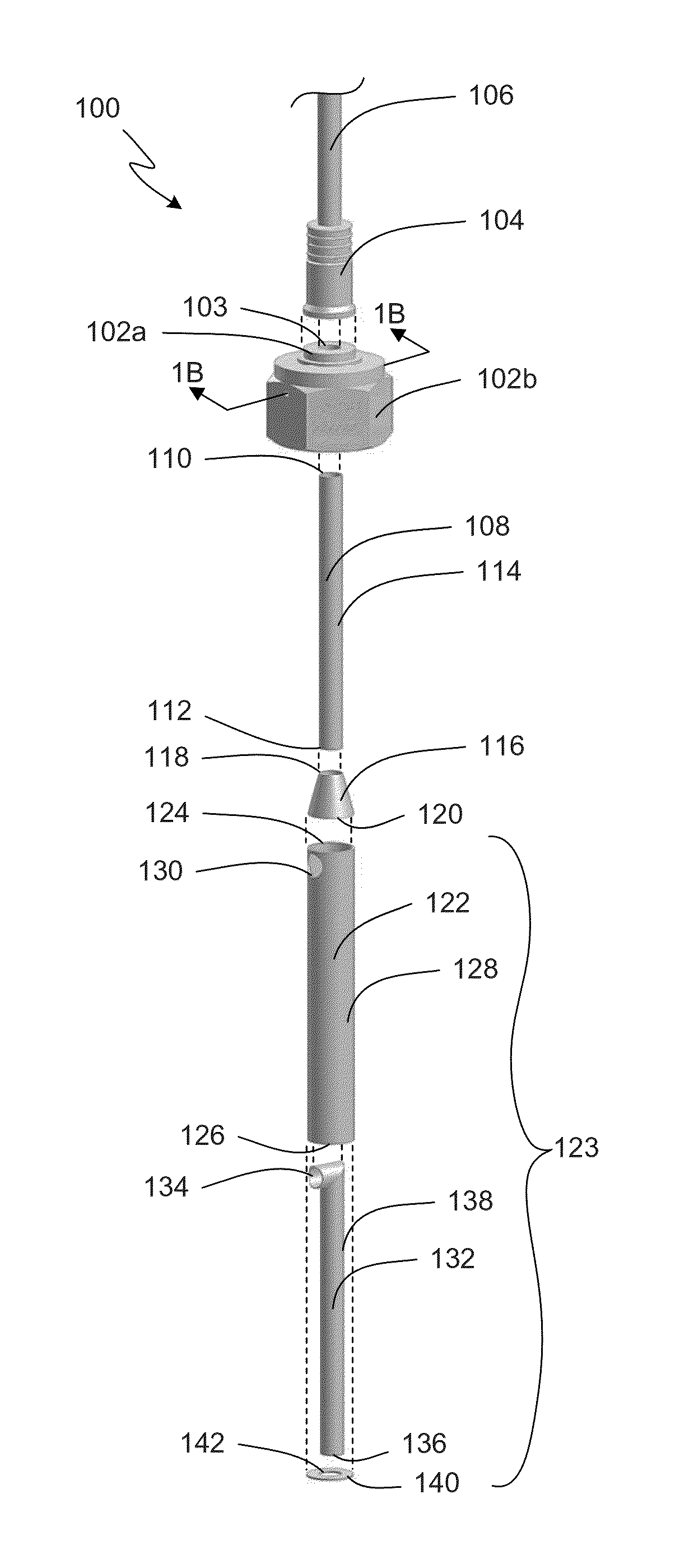
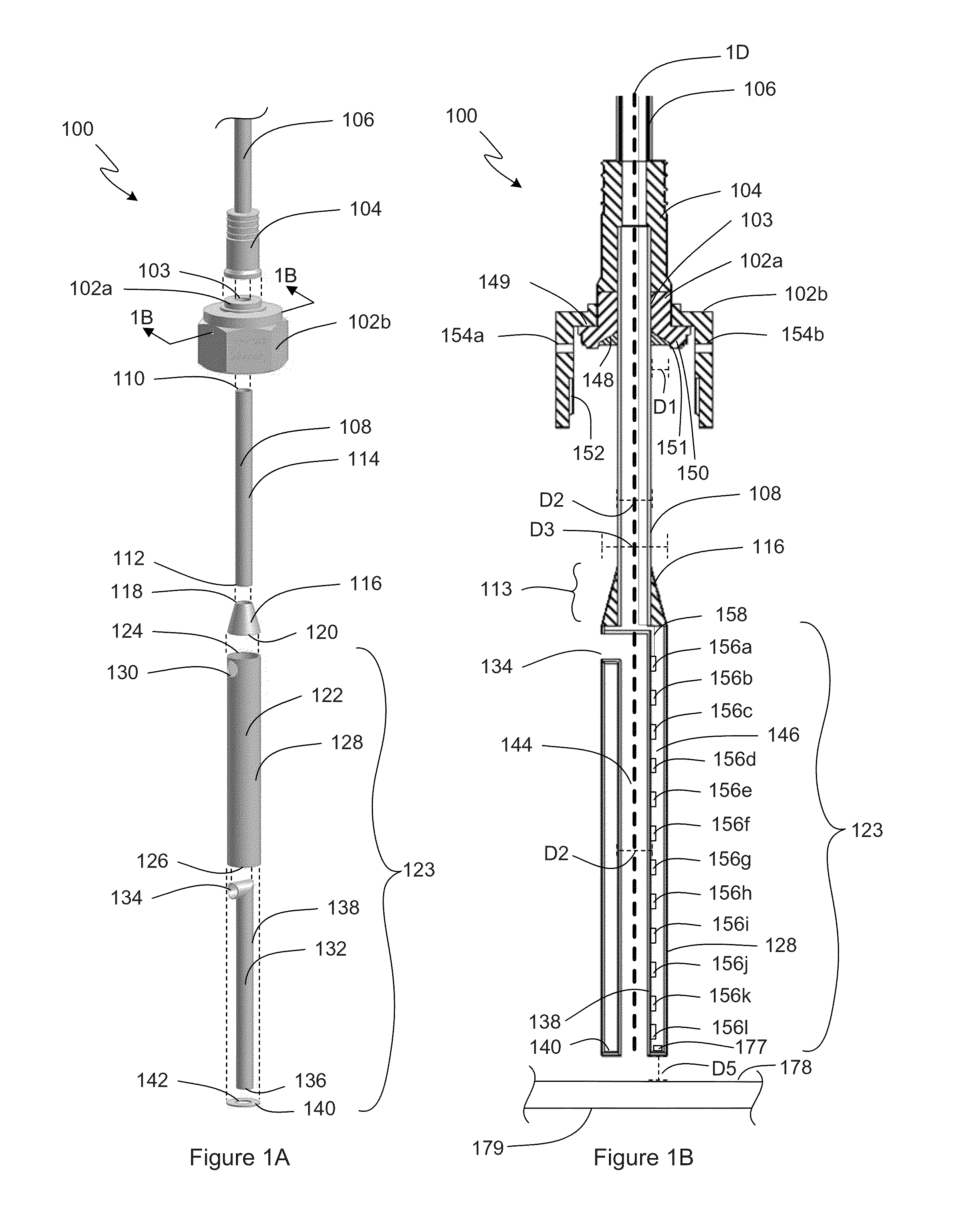
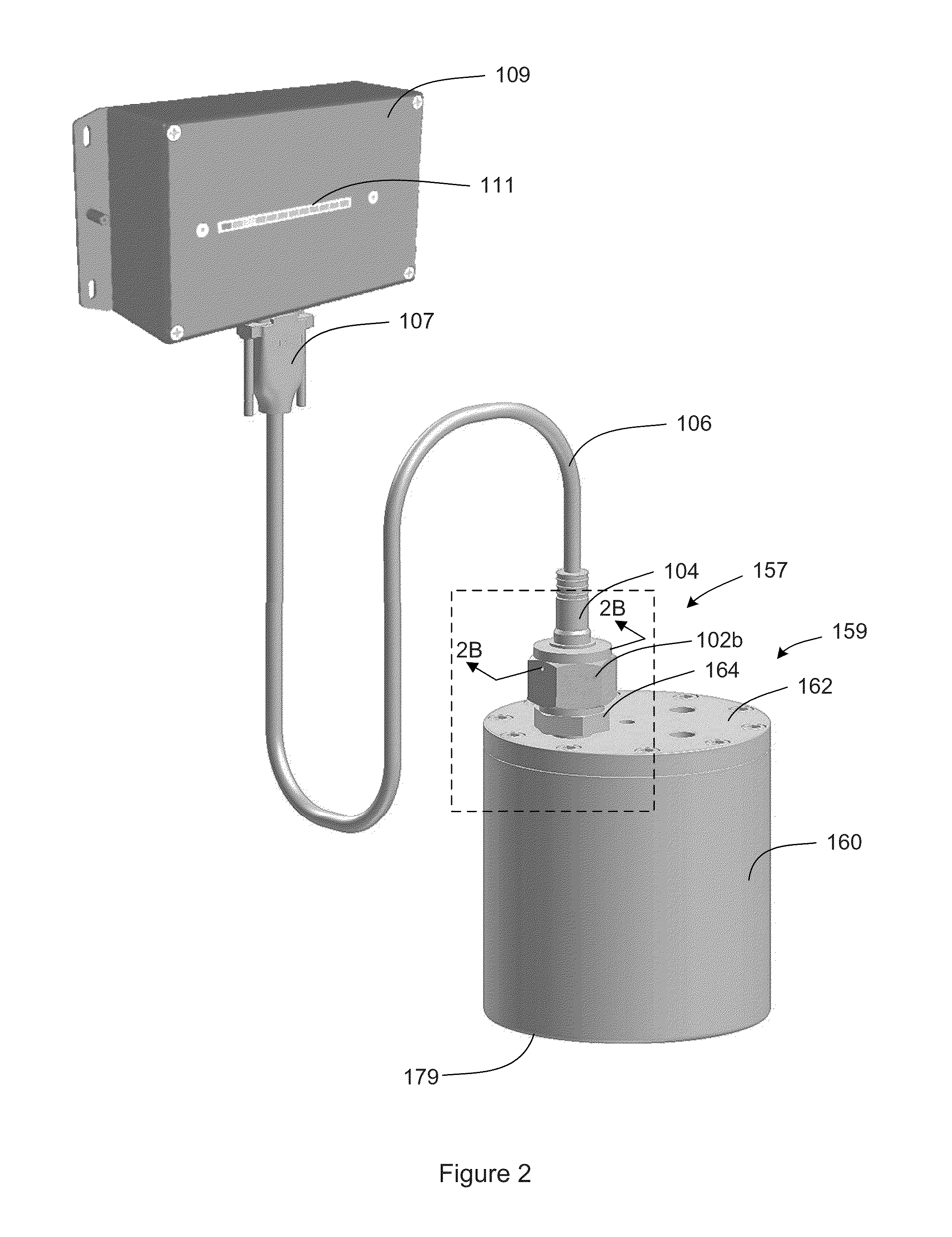
The present invention relates to an ultrasonic probe for sensing the level of liquid in a container. The ultrasonic probe includes an inner tube with an internal volume defined by an inner tube and a conduit, and a plurality of ultrasonic sensors located within the internal volume. The ultrasonic sensors are positioned within the inner tube and are oriented to emit sound waves in response to received electronic signals. The ultrasonic sensors can be affixed to the inner tube at different locations and orientations to provide flexibility in sensing the liquid level. The ultrasonic probe can be used in various types of containers and can be coupled to a controller for sending and receiving electronic signals. The technical effects of the invention include improved accuracy in sensing liquid levels in containers and increased flexibility in installation of the ultrasonic probe.

Problems solved by technology

However such sensors are limited in that they cannot accurately measure chemical reagent levels that are near or below the lower end of the probe.
This presents a problem because of the exacting nature of semiconductor manufacturing processes and environments, the cost associated with the chemical reagents and the cost associated with disposing of leftover chemical reagent when cleaning the containers.

Method used


Image

  • Ultrasonic liquid level sensing systems
  • Ultrasonic liquid level sensing systems
  • Ultrasonic liquid level sensing systems

Examples


Embodiment Construction

[0042]The ensuing detailed description provides preferred exemplary embodiments only, and is not intended to limit the scope, applicability, or configuration of the invention. Rather, the ensuing detailed description of the preferred exemplary embodiments will provide those skilled in the art with an enabling description for implementing the preferred exemplary embodiments of the invention. Various changes may be made in the function and arrangement of elements without departing from the spirit and scope of the invention, as set forth in the appended claims.

[0043]In the figures, elements that are similar to those of other embodiments of the present invention are represented by reference numerals increased by a value of 100. Such elements should be regarded as having the same function and features unless otherwise stated or depicted herein, and the discussion of such elements may therefore not be repeated for multiple embodiments.

[0044]The term “conduit,” as used in the specification...


PUM


Abstract

An ultrasonic probe having ultrasonic sensors (e.g., piezoelectric crystals) for measuring the level of liquid within a sealed container and having features that make the probe more reliable and enable more precise liquid level readings as the container nears an empty state. Embodiments include spacing the ultrasonic sensors more closely at the lower end of the probe, offsetting the sensors to enable tighter vertical spacing, matched pairs of sensors for redundancy, and a downward facing sensor located at the lower end of the probe to decrease the minimum liquid level that can be accurately measured by the probe. A sump may also be provided to further decrease the minimum liquid level that can be accurately measured by the probe.

Description

CROSS REFERENCE TO RELATED APPLICATIONS[0001]The application claims the benefit of U.S. Provisional Application No. 62 / 043,668, filed on Aug. 29, 2014. Co-pending U.S. patent application Ser. No. 14 / 163,407, filed Jan. 24, 2014 is incorporated by reference as if fully set forth.BACKGROUND OF THE INVENTION[0002]Semiconductor manufacturing processes involve the use of chemical reagents that must meet strict purity requirements. These liquid chemical reagents are typically contained in sealed containers (e.g., ampoules) to protect against contamination of the chemical reagents and to prevent leakage. The chemical reagents typically require metal containers and container fittings that use metal-on-metal seals to avoid corrosion, contamination, or leakage under elevated pressures. When using a chemical reagent stored in such a container, it is often necessary to be able to determine the amount of chemical reagent left in the container without exposing the chemical reagent to the environm...

Claims


Application Information

Patent Timeline
IPC IPC(8): G01F23/296
CPCG01F23/2961G01F23/296G01F23/2965
Inventor BIRTCHER, CHARLES, MICHAELSTEIDL, THOMAS, ANDREW
Owner VERSUM MATERIALS US LLC
Learn More