Tillage device for agricultural machinery or implements to reduce compaction caused by wheels in a field

a technology of agricultural machinery or implements and tillage devices, which is applied in the direction of adjusting devices, soil-working methods, agricultural tools and machines, etc., can solve the problems of increasing the size of agricultural implements, increasing the amount of compaction, and less farmer's crop yield, so as to achieve the effect of decompressing and effectively fractured soil layers

Active Publication Date: 2016-03-17
AGRI CONCEPTS
View PDF22 Cites 13 Cited by
  • Summary
  • Abstract
  • Description
  • Claims
  • Application Information

AI Technical Summary

Benefits of technology

[0029]The invention, in this particular form, consists of a moving linkage that allows the tillage device to raise and lower into and out of the soil, a tilling mechanism that effectively fractures and decompresses the compacted layers of soil, and a method of attachment to machine or implement, and the ability to be disengaged the system from use independent of the implement or machine it is attached to.

Problems solved by technology

While the improvements in technology, and the increased size of agricultural implements has allowed farmers to operate more and more land, the increasing size of agricultural implements has its disadvantages.
As the weight of the agricultural implement increases, so increases the amount of compaction caused by the wheels supporting the agricultural implement as it drives through the field.
The more compacted the soil becomes, the less farmer's crops yield because compaction prevents plants roots from dispersing through the soil.
While this arrangement allows a farmer to plant a huge amount of land in an extremely efficient manner, the increased weight of the planter plus the large amount of seed it is carrying, causes severe compaction in the field.
This compaction comes at an extremely vulnerable time for the crop as the seed has just been planted and must quickly germinate, root, and penetrate the soil otherwise it will perish.
Solutions to this problem have been elusive.
However, deep tillage or ripping of the soil has traditionally required a tremendous amount of horsepower and / or torque.
With the use of modern planters that are large and heavy, the pulling tractor is already taxed to the point where adding features that cause large amounts of additional drag on the planters is extremely undesirable.
While adding more wheels resolves some of the compaction, it is extremely expensive and complicated to add additional weight bearing wheels to already complex equipment.
In addition, adding wheels causes additional compaction in other areas.
As such, the addition of more wheels is no solution at all and in-fact can cause further problems, and can reduce the farmer's yield more than the conventional arrangement where the ground under the implement's wheels is essentially sacrificed.
While tracks effectively spread the weight of the tractor and planter over more area, which reduces compaction it comes at the cost of maneuverability.
Tracks also have a tendency to greatly disturb and damage the field when the implement is turned at the end rows of the field because the tracks tear or berm the soil.
As such, what is often gained from a compaction standpoint is often lost in maneuverability and damage to the field standpoint.

Method used


Image

  • Tillage device for agricultural machinery or implements to reduce compaction caused by wheels in a field
  • Tillage device for agricultural machinery or implements to reduce compaction caused by wheels in a field
  • Tillage device for agricultural machinery or implements to reduce compaction caused by wheels in a field

Examples


first embodiment

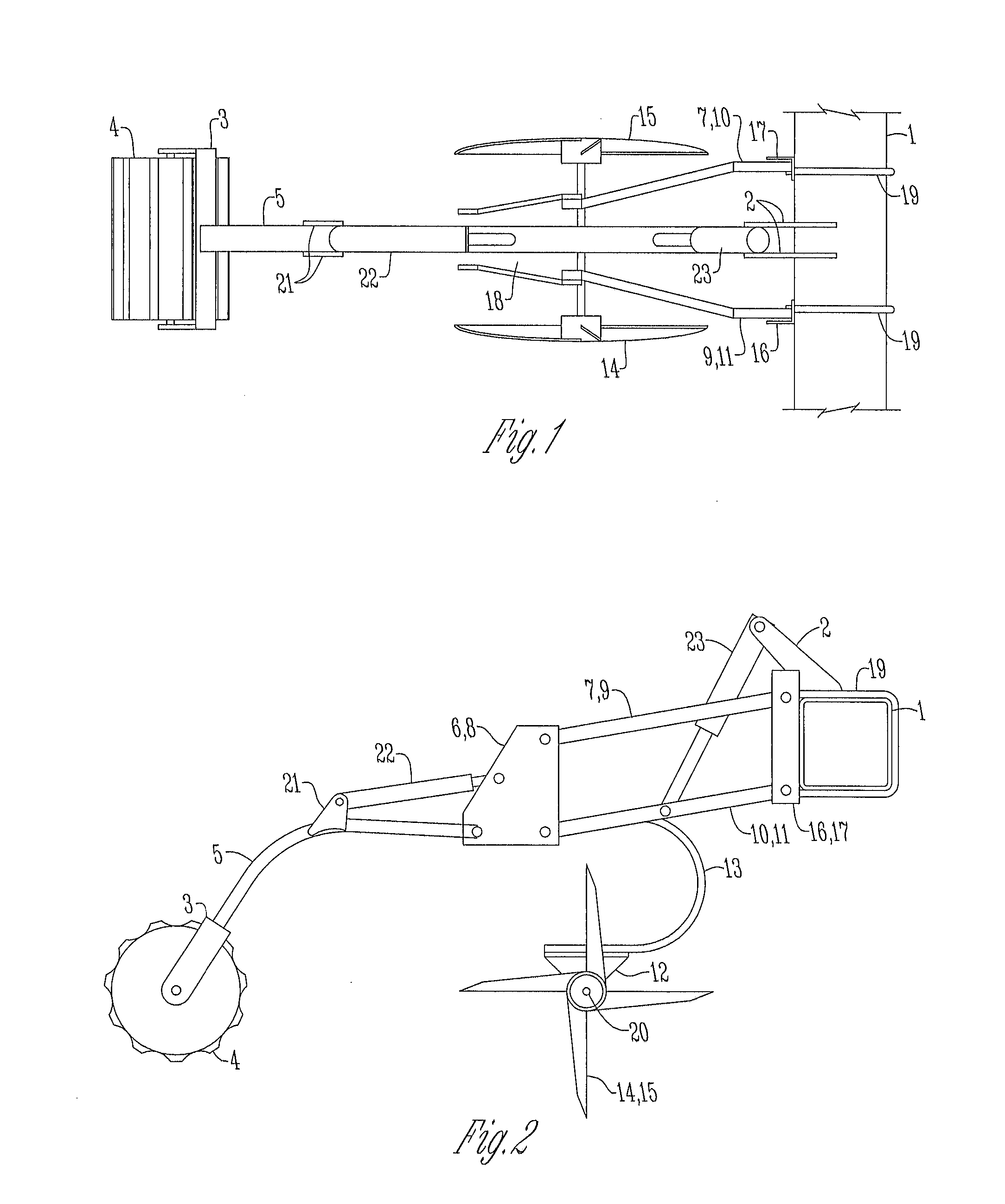
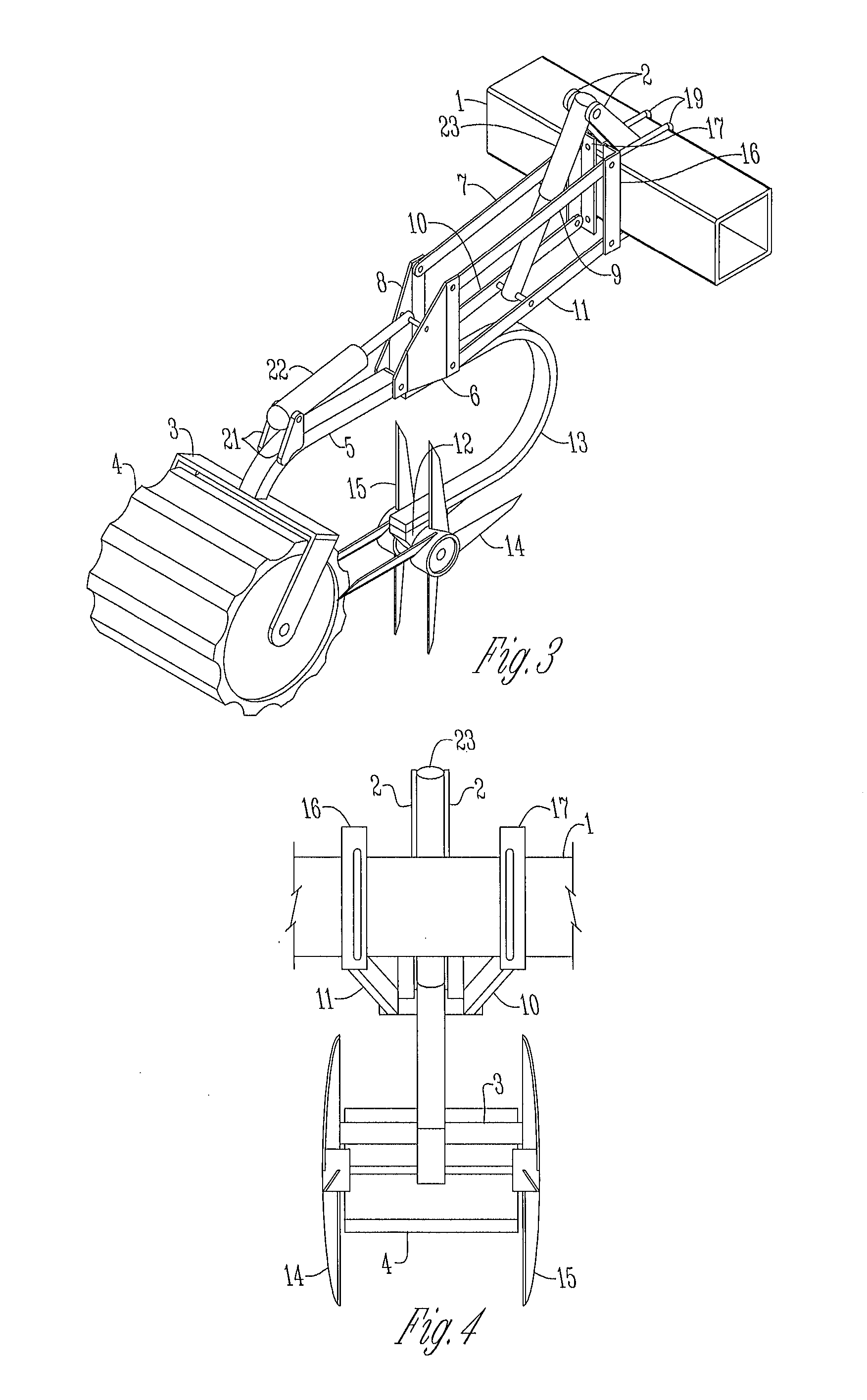
[0062]In FIGS. 1-5, show a tillage device 28 bolted to the frame 1 of an agricultural implement 30. The tillage device 28 includes four linkage arms 7, 9, 10, 11 attach to the left and right angle iron 16, 17 with pins to allow vertical movement of the linkage arms 7, 9, 10, 11. The angle iron 16, 17 is mounted to the frame 1 of the agricultural implement 30 with U-bolts 19. A hydraulic cylinder 23 extends between the linkage arms 7, 9, 10, 11 and serves to raise and lower the linkage arms 7, 9, 10, 11 when actuated. The hydraulic cylinder 23 connects at its upper end to a pair of mounting plates, 2 fitted to the frame 1. The hydraulic cylinder 23 connects to the inside of the lower linkage arms 7, 9 adjacent its lower end. The linkage arms 7, 9, 10, 11 extend from the angle iron 16, 17 at their upper ends to the two rear mounting plates 6, 8 at their lower ends.

[0063]Between these two rear mounting plates 6, 8, the C-spring mount 18 is secured and attached to the C-spring 13, adjac...

second embodiment

[0064]FIGS. 6-10 depict a second embodiment, of a tillage device 28 which is similarly mounted to the frame 1 of an agricultural implement 30 as is shown in FIGS. 1-5 and includes many of the same components and arrangement of parts as is shown and described with respect to the first embodiment. In this arrangement, the rolling aeration spikes 14, 15 are replaced with coulters 25, which are formed in the shape of disks instead of having a plurality of spikes or tines. This embodiment also includes a shank 24 which points forward toward frame 1 and includes a removable shovel or point 26 attached to the lower end of the shank 24. The upper end of shank 24 is connected to the rear mounting plates 6, 8. FIGS. 6-10 also depict a spring-loaded tension rod 22 which connects to the rear plates 6, 8 and the spring mount 21 on the shank 24.

[0065]In this proposed embodiment, bolting the tillage device 28 to the frame 1 of an agricultural implement 30 will secure the tillage device 28 to the a...

third embodiment

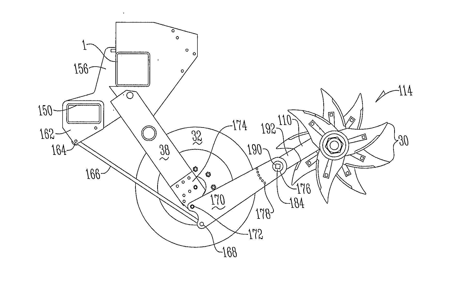
[0070]An alternative third embodiment is presented with reference to FIGS. 11-15. This third embodiment is often used when it is required to position the tillage device 28 between row units of a planter. In this third embodiment, the tillage device 28 includes a pair of mounting plates 50 that are positioned in generally parallel spaced relation to one another. Mounting plates 50 are generally flat and planar in shape and include a number of openings and features as are described herein. Frame mounting members 52 are connected to the upper forward edge of mounting plates 52 and serve to connect to and hold the tube frame 1 of the agricultural implement 30.

[0071]Frame mounting members 52 include a generally L-shaped lower portion 54. The L-shaped lower portion 54 is connected to the mounting plates 50 by any means such as welding, screwing, bolting or forming the two components out of a single piece of material. The L-shaped lower portion 54 defines two sides of the square of the tub...


PUM


Abstract

A system for tilling compression marks formed in a field by wheels of agricultural machinery the system including a first roller assembly having a plurality of blade assemblies positioned in spaced relation to one another. The first roller assembly rotatably connected to a swing arm which moves the first roller assembly between a disengaged position, where the roller assembly does not penetrate the soil, and an engaged position where the roller assembly does penetrate and till the soil. The first roller assembly is positioned behind and in alignment with a first wheel of the agricultural machinery such that the first roller assembly tills the compression mark formed by the first wheel.

Description

CROSS REFERENCE TO RELATED APPLICATION[0001]This continuation-in-part application claims the benefit of U.S. Utility application Ser. No. 14 / 109,588 filed Dec. 17, 2013 and U.S. Provisional Application No. 61 / 739,303 filed Dec. 19, 2012.FIELD OF THE INVENTION[0002]This invention relates to agricultural machinery and implements. More specifically, and without limitation, this invention relates to a tillage device for agricultural machinery and implements that reduces the compaction in a field caused by wheels which support the agricultural machinery or implement.BACKGROUND[0003]Improvements in machinery and technology have drastically changed agricultural practices. As machinery and technology has improved, this has allowed farmers to grow the size of their operations. As the number of acres a farmer must plant, fertilize, spray and harvest increases, so must grow the size and capacity of the farmer's agricultural implements. The term “agricultural implement” and / or “agricultural mac...

Claims


Application Information

Patent Timeline
Patent Type & Authority Applications(United States)
IPC IPC(8): A01B37/00
CPCA01B37/00A01B35/16A01B49/02
Inventor HURD, COLIN, JOSH
Owner AGRI CONCEPTS
Why Eureka
Try Eureka