Tillage device for agricultural machinery or implements to reduce compaction caused by wheels in a field
- Summary
- Abstract
- Description
- Claims
- Application Information
AI Technical Summary
Benefits of technology
Problems solved by technology
Method used
Image
Examples
first embodiment
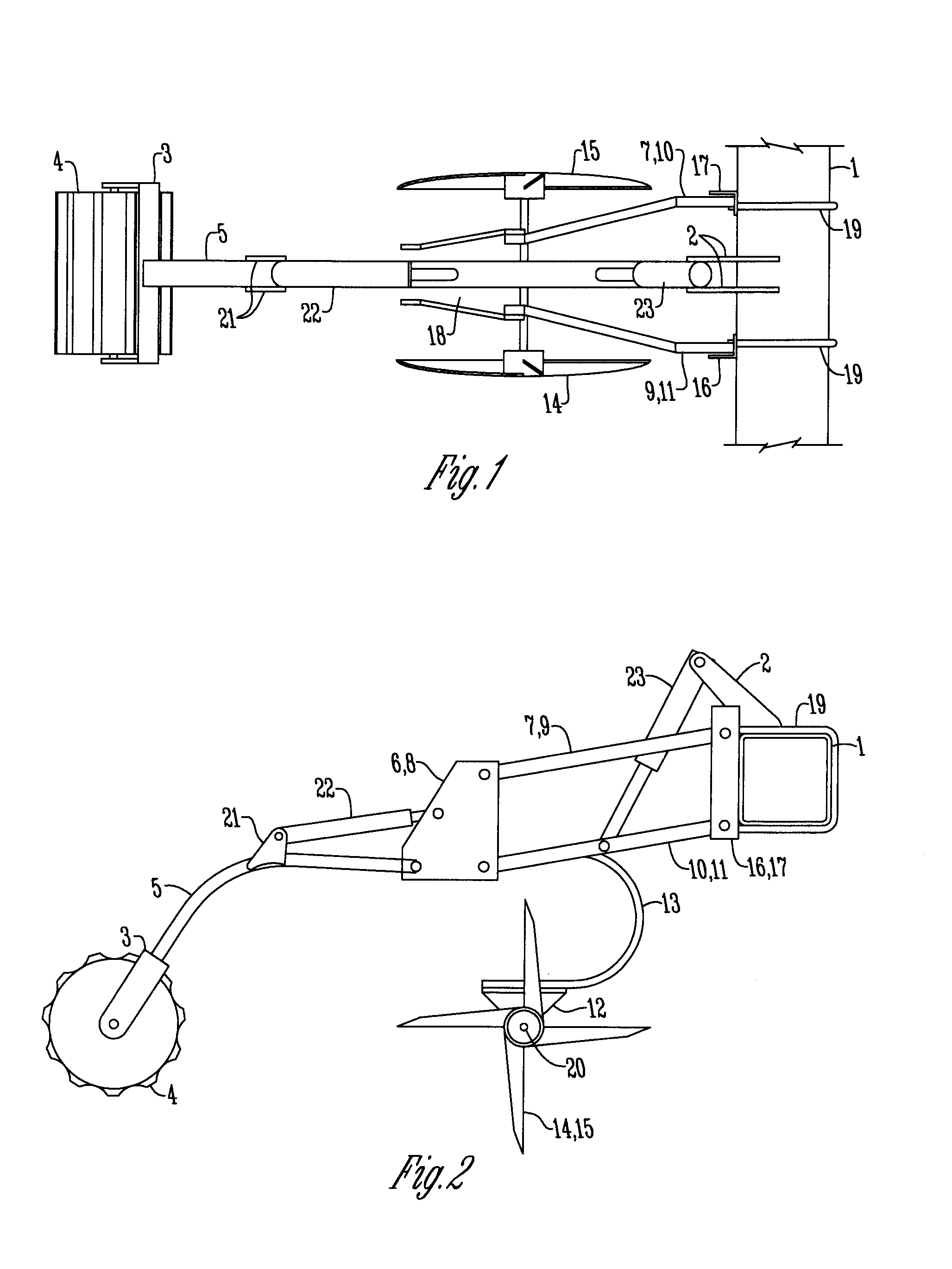
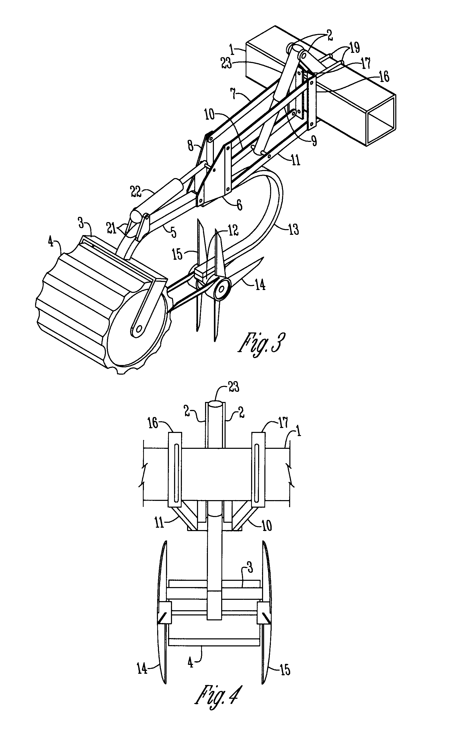
[0053]In FIGS. 1-5, show a tillage device 28 bolted to the frame 1 of an agricultural implement 30. The tillage device 28 includes four linkage arms 7, 9, 10, 11 attach to the left and right angle iron 16, 17 with pins to allow vertical movement of the linkage arms 7, 9, 10, 11. The angle iron 16, 17 is mounted to the frame 1 of the agricultural implement 30 with U-bolts 19. A hydraulic cylinder 23 extends between the linkage arms 7, 9, 10, 11 and serves to raise and lower the linkage arms 7, 9, 10, 11 when actuated. The hydraulic cylinder 23 connects at its upper end to a pair of mounting plates, 2 fitted to the frame 1. The hydraulic cylinder 23 connects to the inside of the lower linkage arms 7, 9 adjacent its lower end. The linkage arms 7, 9, 10, 11 extend from the angle iron 16, 17 at their upper ends to the two rear mounting plates 6, 8 at their lower ends.
[0054]Between these two rear mounting plates 6, 8, the C-spring mount 18 is secured and attached to the C-spring 13, adjac...
second embodiment
[0055]FIGS. 6-10 depict a second embodiment, of a tillage device 28 which is similarly mounted to the frame 1 of an agricultural implement 30 as is shown in FIGS. 1-5 and includes many of the same components and arrangement of parts as is shown and described with respect to the first embodiment. In this arrangement, the rolling aeration spikes 14, 15 are replaced with coulters 25, which are formed in the shape of disks instead of having a plurality of spikes or tines. This embodiment also includes a shank 24 which points forward toward frame 1 and includes a removable shovel or point 26 attached to the lower end of the shank 24. The upper end of shank 24 is connected to the rear mounting plates 6, 8. FIGS. 6-10 also depict a spring-loaded tension rod 22 which connects to the rear plates 6, 8 and the spring mount 21 on the shank 24.
[0056]In this proposed embodiment, bolting the tillage device 28 to the frame 1 of an agricultural implement 30 will secure the tillage device 28 to the a...
third embodiment
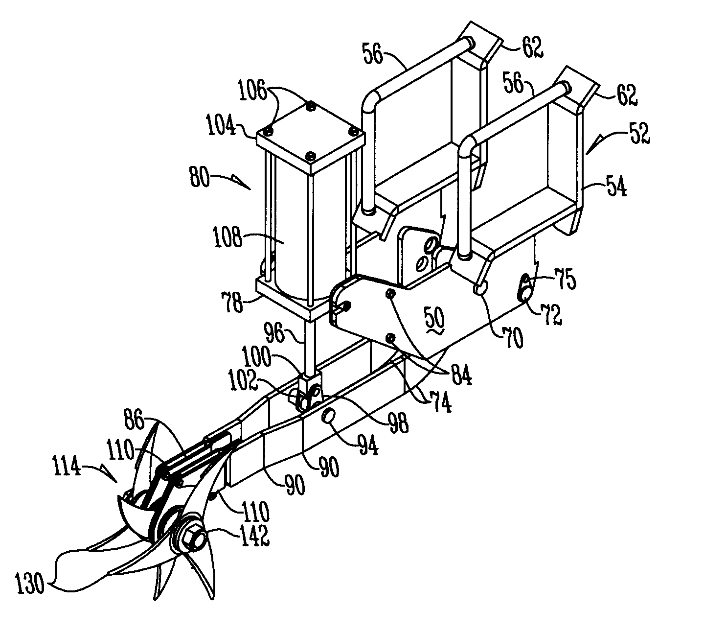
[0061]An alternative third embodiment is presented with reference to FIGS. 11-15. This third embodiment is often used when it is required to position the tillage device 28 between row units of a planter. In this third embodiment, the tillage device 28 includes a pair of mounting plates 50 that are positioned in generally parallel spaced relation to one another. Mounting plates 50 are generally flat and planar in shape and include a number of openings and features as are described herein. Frame mounting members 52 are connected to the upper forward edge of mounting plates 52 and serve to connect to and hold the tube frame 1 of the agricultural implement 30.
[0062]Frame mounting members 52 include a generally L-shaped lower portion 54. The L-shaped lower portion 54 is connected to the mounting plates 50 by any means such as welding, screwing, bolting or forming the two components out of a single piece of material. The L-shaped lower portion 54 defines two sides of the square of the tub...
PUM
 Abstract
Description
Claims
Application Information
 - R&D
- Intellectual Property
- Life Sciences
- Materials
- Tech Scout
- Unparalleled Data Quality
- Higher Quality Content
- 60% Fewer Hallucinations
Browse by: Latest US Patents, China's latest patents, Technical Efficacy Thesaurus, Application Domain, Technology Topic, Popular Technical Reports.
© 2025 PatSnap. All rights reserved.Legal|Privacy policy|Modern Slavery Act Transparency Statement|Sitemap|About US| Contact US: help@patsnap.com


