
Space Structure Deployment System

a technology for space structures and deployment systems, applied in the field of space structures, can solve the problems of satellites falling after, satellites falling, and not including these types of systems to reduce size, weight, or both in the satelli

Active Publication Date: 2016-03-17
THE BOEING CO
View PDF13 Cites 20 Cited by
  • Summary
  • Abstract
  • Description
  • Claims
  • Application Information

AI Technical Summary

Benefits of technology

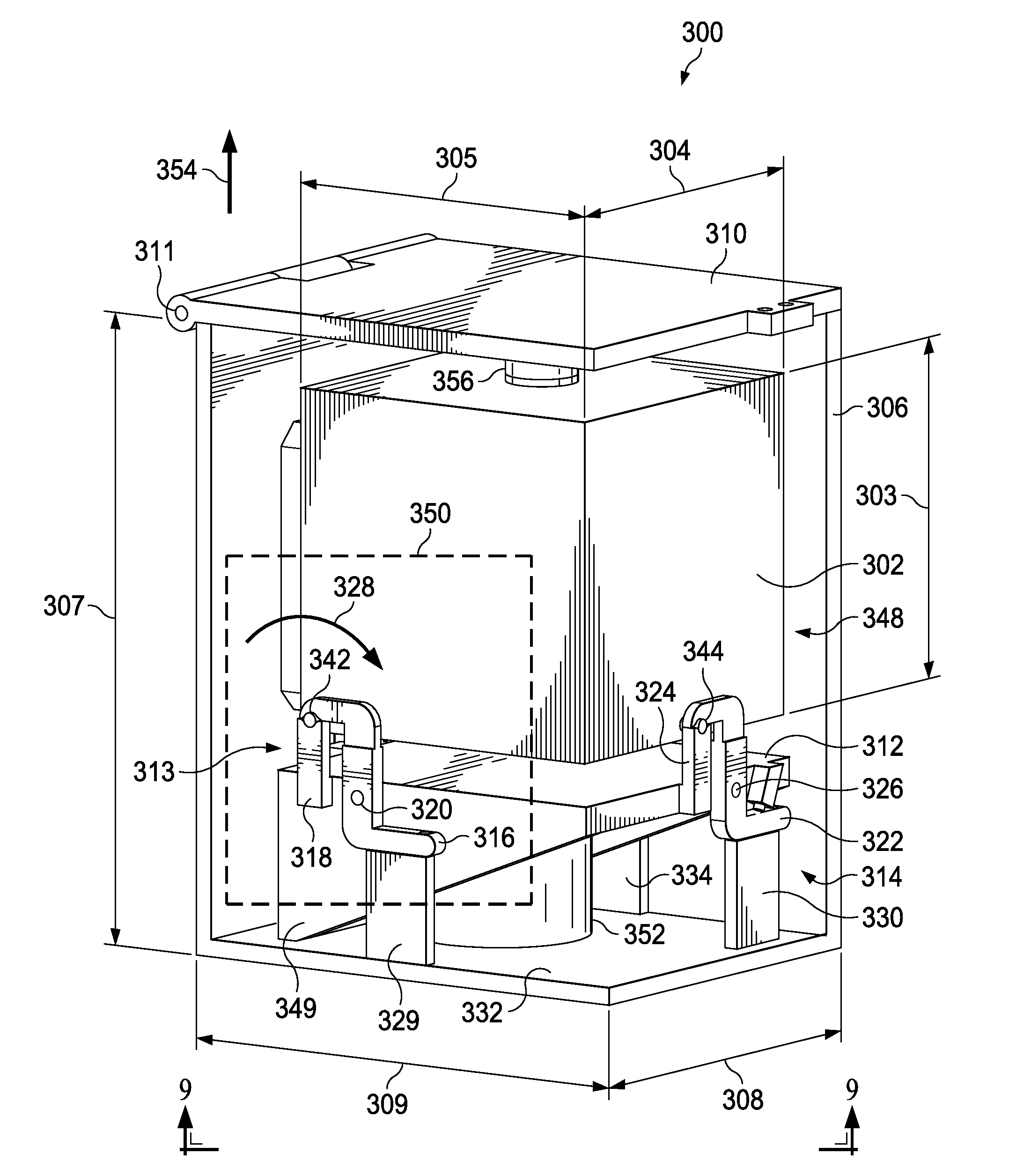
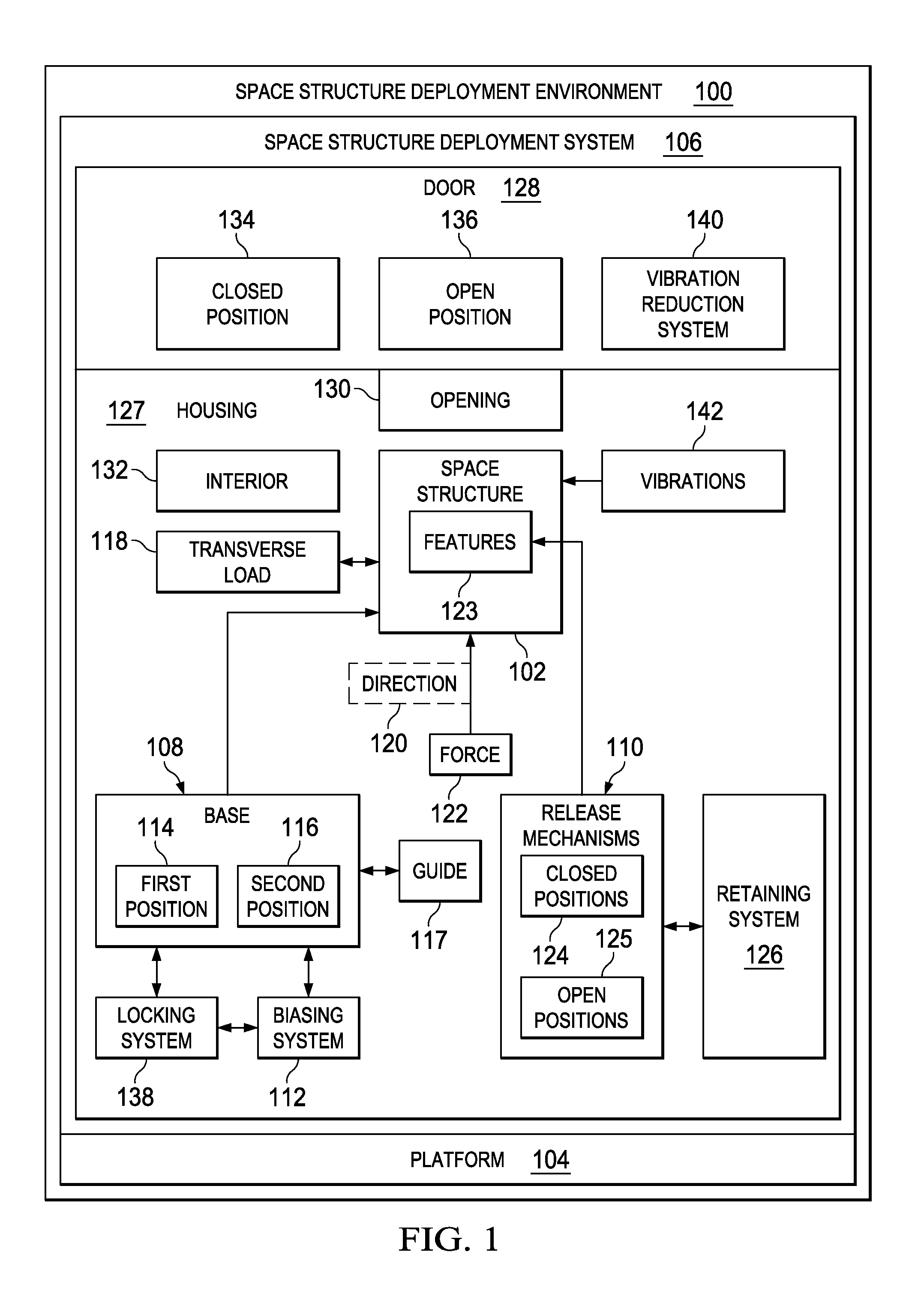
This patent describes a way to deploy a space structure using a base and release mechanisms. When the base is in the first position, the release mechanisms engage with features on the space structure to secure it. When the base is moved to a second position, the release mechanisms disengage from the features to release the space structure without causing any additional pressure in the direction it is moving. This provides a way to safely and smoothly deploy space structures without causing any damage.

Problems solved by technology

Depending on the conditions and systems used during deployment, the satellite may tumble after separation from the launch vehicle.
The potential for uneven force distribution applied to separate the satellite from the launch vehicle from these different points may be such that the satellite tumbles.
Smaller satellites, however, may not include these types of systems to reduce size, weight, or both in the satellite.
As a result, tumbling that may occur from deployment may exceed the torque authority of other attitude control actuators, like reaction wheels, and may therefore result in tumble rates that cannot be effectively reduced or eliminated by the cubesat subsystems.

Method used


Image

  • Space Structure Deployment System
  • Space Structure Deployment System
  • Space Structure Deployment System

Examples


Embodiment Construction

[0026]The illustrative embodiments recognize and take into account one or more different considerations. For example, the illustrative embodiments recognize and take into account that currently used deployment systems with devices may apply different amounts of force to the satellite. For example, explosive bolts, springs, dampeners, and other devices may provide different amounts of force when used to release a satellite from a platform for deployment of the satellite.

[0027]These types of devices may result in different amounts of force, velocities, or both occurring at different parts of the satellite and potentially at slightly different times. This situation may result in undesired tumbling of the satellite.

[0028]The illustrative embodiments provide a solution to the technical problem involving undesired tumbling of a space structure, such as a satellite. Further, the illustrative embodiments provide a method and apparatus for deploying a space structure. In one illustrative emb...


PUM


Abstract

A method and apparatus for deploying a space structure. The space structure is secured to a base with release mechanisms that engage features of the space structure when the base is in a first position. The base is moved from the first position to a second position to deploy the space structure. The release mechanisms are moved at substantially a same time to disengage from the features and release the space structure from the base without imparting a transverse load to the space structure when the base moves from the first position towards the second position to deploy the space structure.

Description

BACKGROUND INFORMATION[0001]1. Field[0002]The present disclosure relates generally to space structures and, in particular, to deploying space structures. Still more particularly, the present disclosure is related to a method and apparatus for deploying a space structure, such as a satellite.[0003]2. Background[0004]Launch vehicles may be used to carry payloads, people, or both from the earth into outer space. For example, a launch vehicle may carry a payload such as a satellite into outer space. Once the launch vehicle has reached a desired distance from the earth for deployment of the satellite, the satellite is separated from the launch vehicle through actuation of one or more deployment mechanisms.[0005]Depending on the conditions and systems used during deployment, the satellite may tumble after separation from the launch vehicle. For example, some deployment systems for satellites use explosive bolts or multiple pusher springs to separate the satellite from the launch vehicle. ...

Claims


Application Information

Patent Timeline
IPC IPC(8): B64G1/00B64G1/10
CPCB64G1/10B64G1/005B64G1/64B64G1/228B64G1/6425B64G1/641
Inventor ROBLES, THOMAS E.HOWARD, TREVOR SCOTT
Owner THE BOEING CO
Learn More