Decorative structure and method for same

a technology applied in the field of decorative structure and method for same, can solve the problems of requiring significant structure, heavy permanent ceiling structure, and affecting the appearance of the room,

Active Publication Date: 2016-03-17
EPS SPECIALTIES LTD
View PDF5 Cites 3 Cited by
  • Summary
  • Abstract
  • Description
  • Claims
  • Application Information

AI Technical Summary

Problems solved by technology

Because permanent displays are intended to remain in place for an extended period, permanent displays may be constructed using methods and materials that are relatively labor and cost intensive to produce a durable display.
Permanent ceiling structures are often heavy and therefore require significant structure to support them from a ceiling surface.
It therefore takes additional time and costs to prepare the suspension system for such structures and displays, in addition to assembling or building the actual structure or display itself.
As such, for temporary structures that are suspended from a ceiling, it is not desirable to have a structure that is complicated to build or is heavy or one that requires significant work to a ceiling surface or a costly suspension system to support.

Method used


Image

  • Decorative structure and method for same
  • Decorative structure and method for same
  • Decorative structure and method for same

Examples


Embodiment Construction

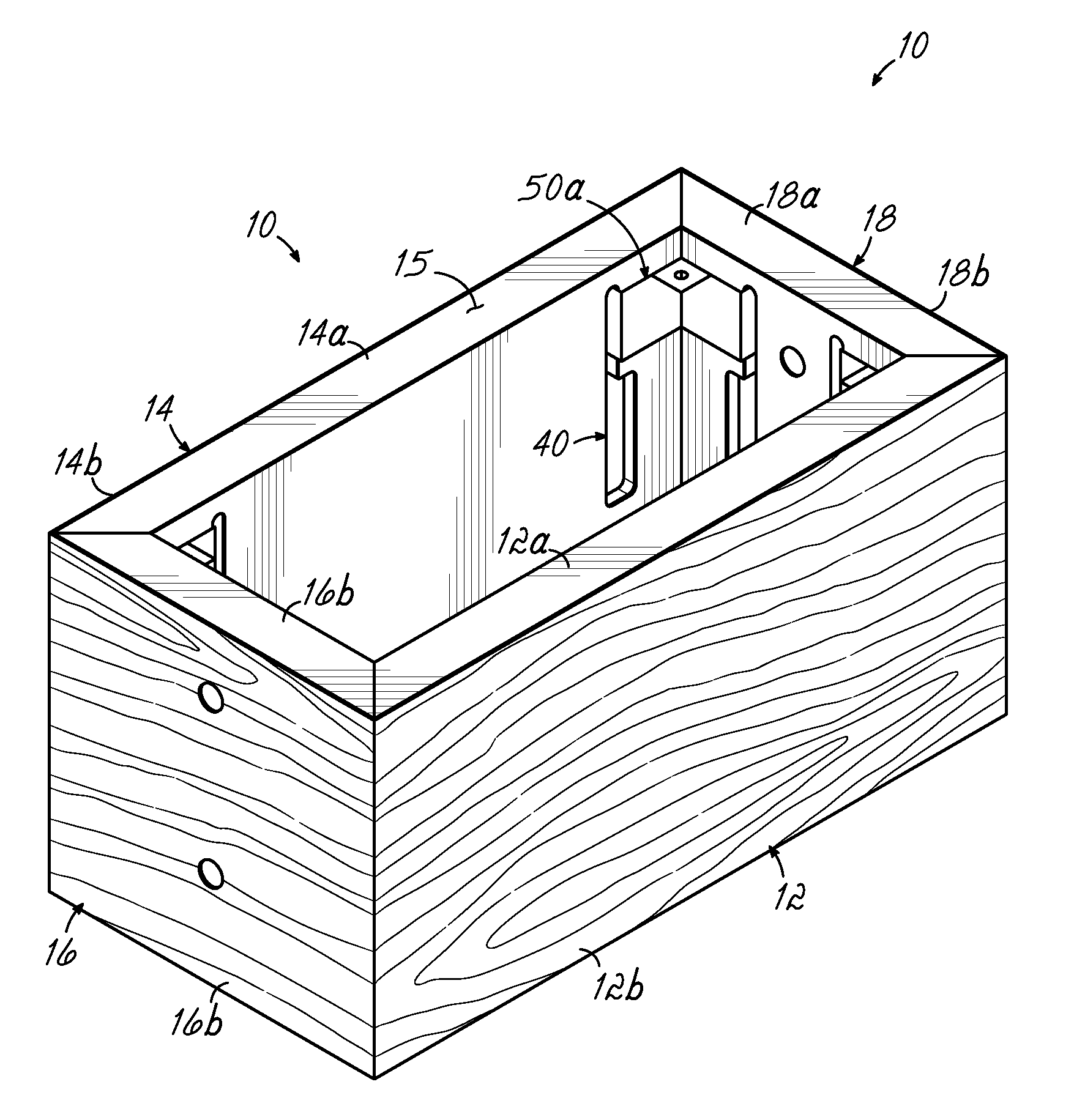
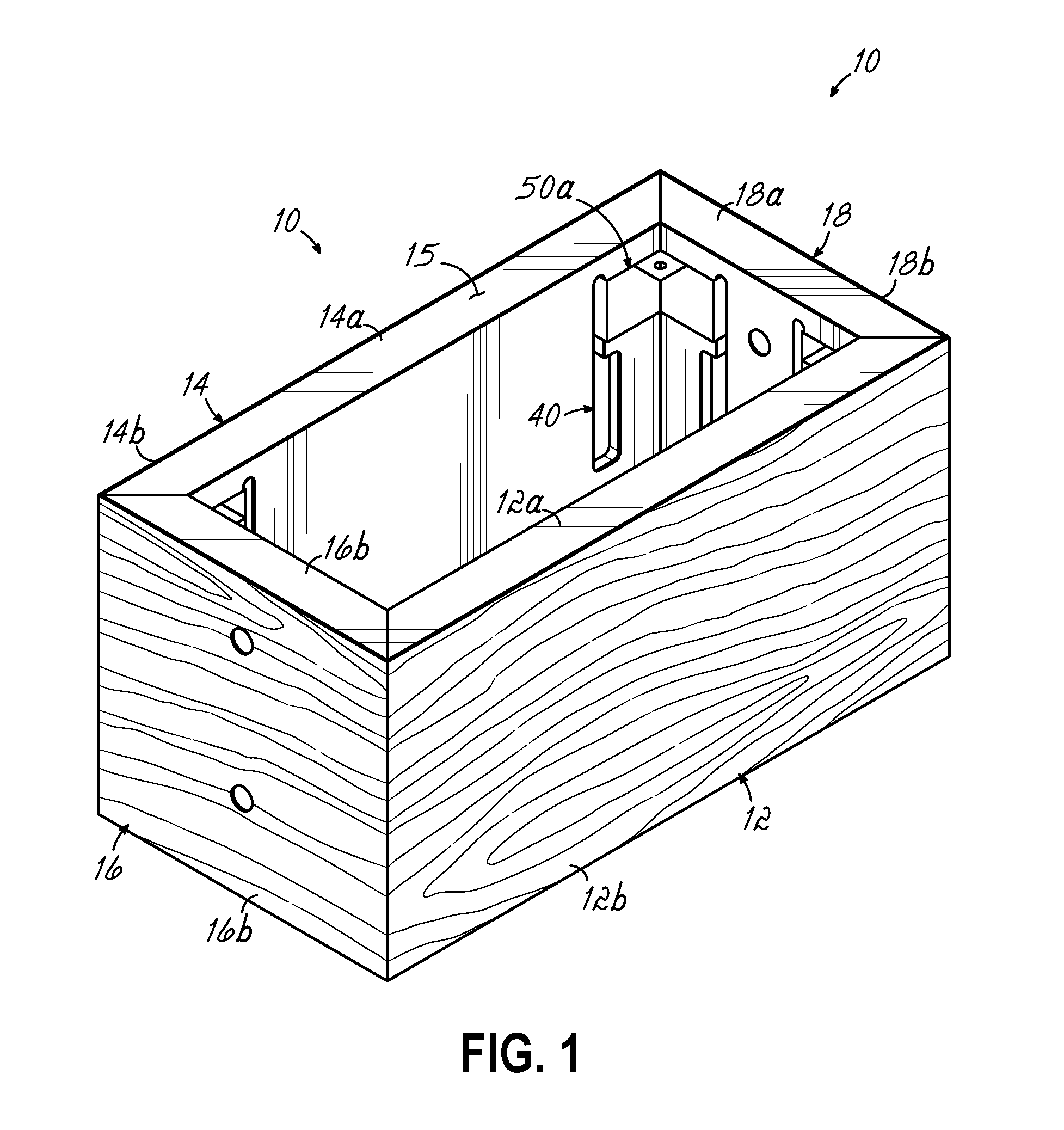
[0023]FIG. 1 illustrates a structure 10 in accordance with one aspect of the invention. Structure 10 is shown in an assembled position as a three-dimensional structure, but is able to be laid flat in an unassembled position, such as for shipment and / or storage. As illustrated herein, the flat, unassembled structure in the form of a blank may lay flat and be folded along fold lines to form the three-dimensional structure 10 illustrated in FIG. 1.

[0024]Structure 10 of FIG. 1 includes side panels 12 and 14, and end panels 16 and 18. Referring to FIGS. 6 and 7, structure 10 also includes a bottom panel 20, coupling the other panels together. As illustrated in FIG. 7, the structure is configured to initially be flat in an unassembled position, and thus, resembles a traditional paper blank. It can be shipped and stored efficiently in that way. Once the various adjacent panels are folded along respective fold lines in the assembled position, the adjacent panels come together to form the th...


PUM


Abstract

A structure is configured to be flat in an unassembled position and to form a three-dimensional structure in an assembled position. The structure includes a plurality of adjacent panels coupled together along fold lines with each panel including a foam core covered on one surface by a flexible skin. The flexible skin is continuous between the adjacent panels that are coupled together for forming a respective fold line for the adjacent panels to be brought together at a right angle to each other along the fold line. The foam core of each panel includes a mitered surface along abutting edges to form a miter joint when adjacent panels are brought together. Slots are formed in the panel cores adjacent to mitered surfaces. Brackets span a miter joint between adjacent panels, holding the spanned miter joint and panels together in a three-dimensional structure.

Description

FIELD OF INVENTION[0001]This invention relates to apparatus and method for forming a structure that might be suspended from a ceiling surface for decorative purposes, signage, displays trellises and the like. More specifically, it relates to structure for providing a three-dimensional platform used to decorate a space or advertise or identify merchandise within a building interior environment.BACKGROUND OF THE INVENTION[0002]Structures are commonly used in retail environments to identify and promote merchandise or generally decorate a space. For example, structures such as interior signage or Point of Purchase (POP) displays are arranged in the interior of a building. Such structures are an effective way to display graphics and capture the attention of retail customers and make a particular product stand out, thereby increasing sales of that product. Also, structures like a trellis may be used to fill in large open spaces, such as in big box stores, to bring the space in or provide ...

Claims


Application Information

Patent Timeline
Patent Type & Authority Applications(United States)
IPC IPC(8): G09F1/06
CPCG09F1/06
Inventor WILKINSON, JR., EDGAR, L.
Owner EPS SPECIALTIES LTD
Why Eureka
Try Eureka