Reverse osmosis push filter with floating key lock

Active Publication Date: 2016-03-24
KX TECH LLC (DW US)
View PDF0 Cites 17 Cited by
  • Summary
  • Abstract
  • Description
  • Claims
  • Application Information

AI Technical Summary

Benefits of technology

The invention provides a reverse osmosis filter housing that is easy to replace and remove. It also allows for a keyed identification of the filter.

Problems solved by technology

Although these patents show filters for water filtration, the filters are difficult to replace owing to their design and placement.
The filter access is coplanar with the refrigerator wall and forces an awkward access to the filter cartridge.
As discussed further herein, a reverse osmosis design requires an additional port, making the attachment scheme more complex than that of a simple filter cartridge system for typical refrigerator use.
However, the extra port and additional water disposal means requires added complexity during attachment and detachment, which the present design facilitates

Method used


Image

  • Reverse osmosis push filter with floating key lock
  • Reverse osmosis push filter with floating key lock
  • Reverse osmosis push filter with floating key lock

Examples


first embodiment

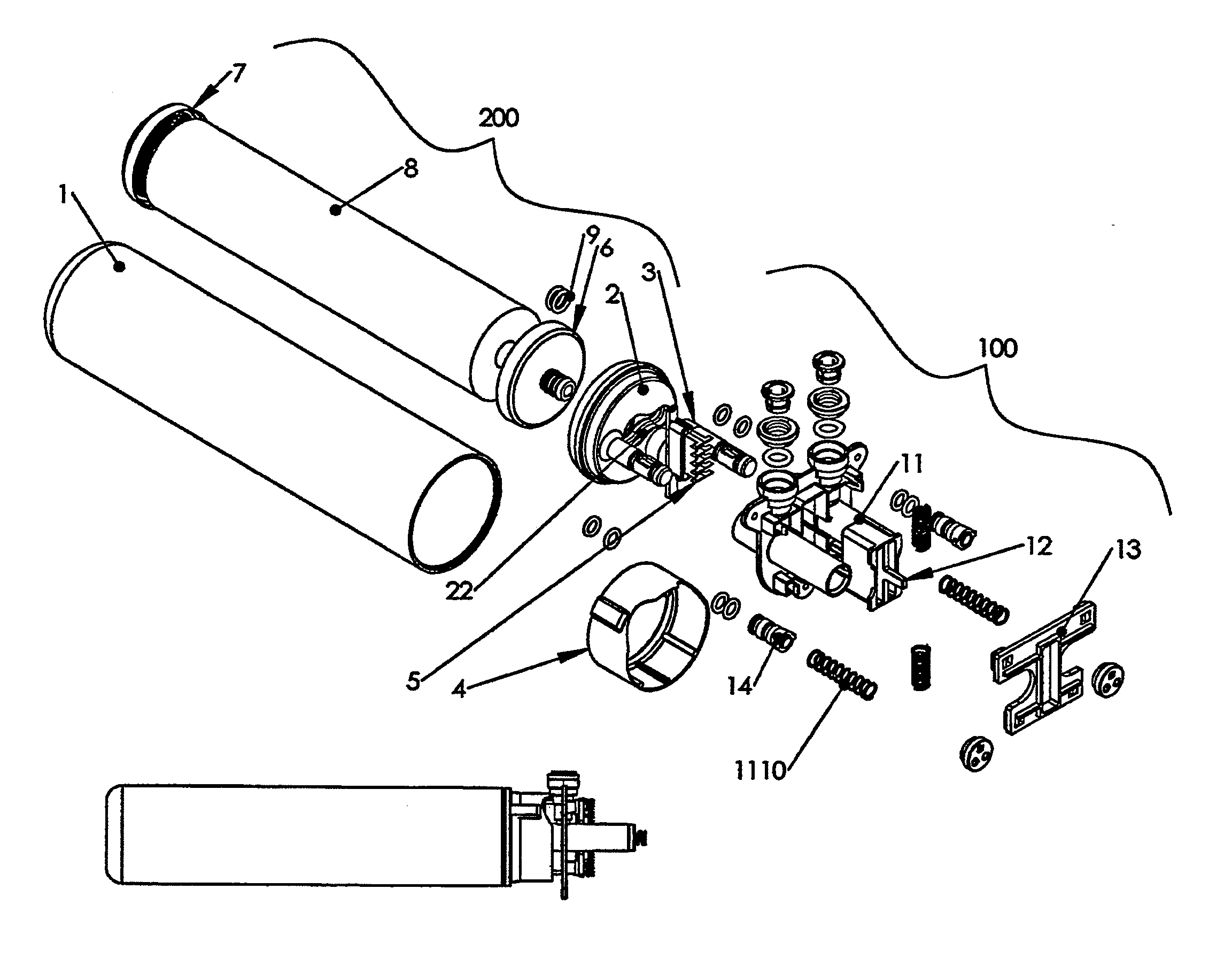
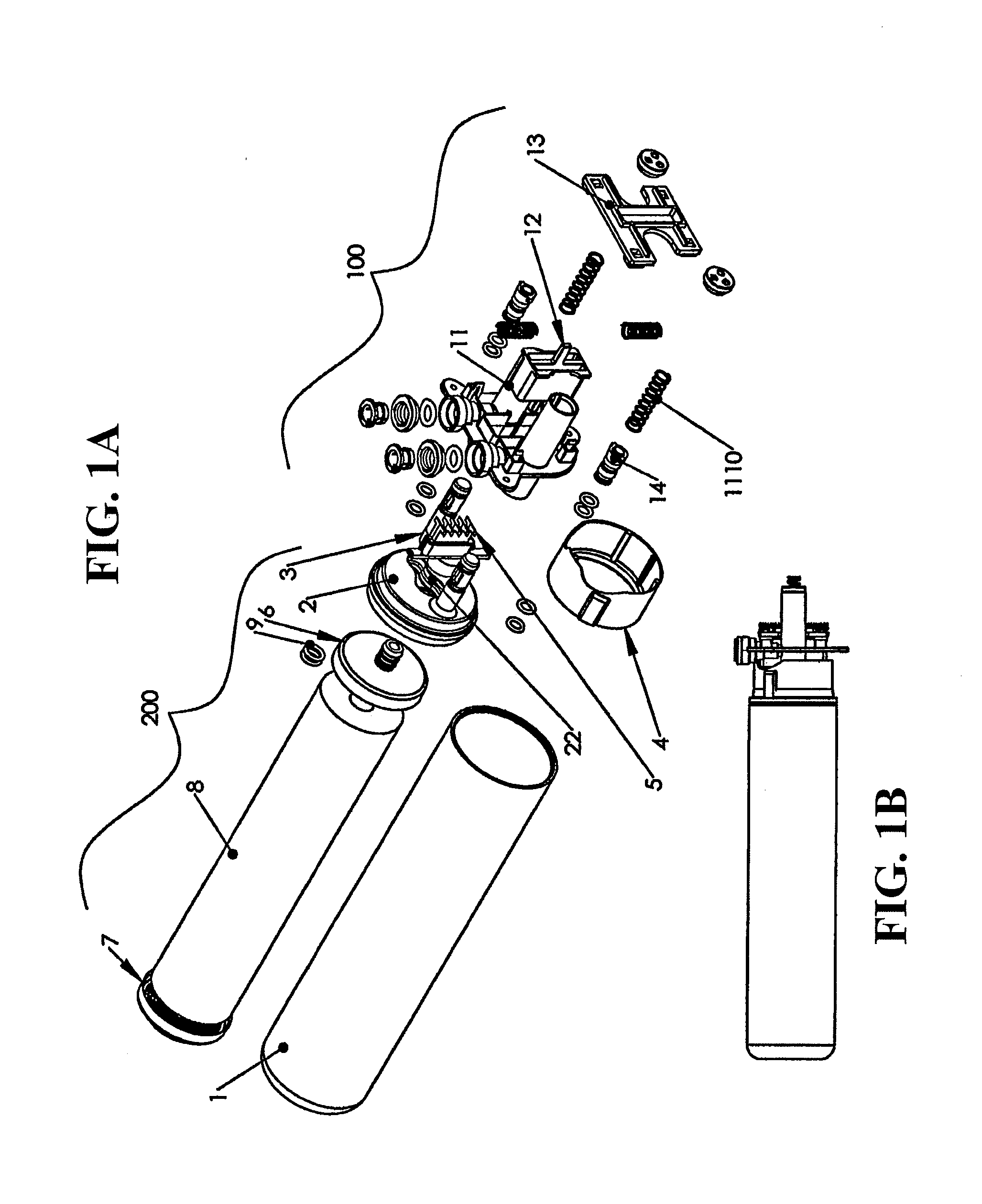
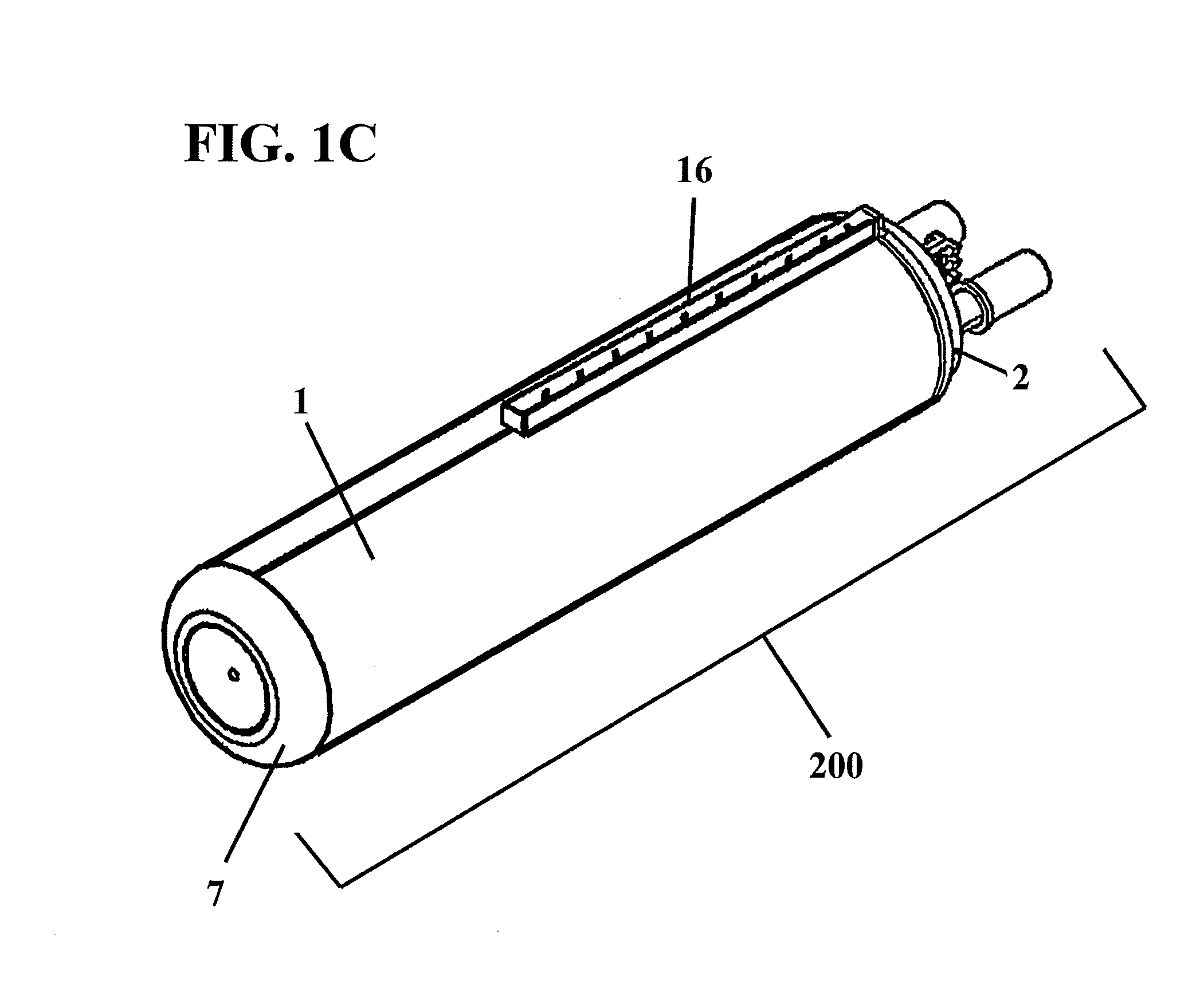
[0097]In a first embodiment, a filter housing assembly 200 comprises the removable, detachable filter cartridge or sump of the filter assembly from a filter base 100. It should be noted that many of the features perform in the same manner if the attachment scheme is presented in the radial direction. Filter housing assembly 200 includes a filter housing 1, which encloses filter media 8, a filter head 2 that attaches at one end to filter housing 1, and attaches at the other end to a filter manifold 3 and non-floating port 11. A filter key 5 is attached to filter manifold 3. Filter base 100 includes non-floating port 11, floating lock 12, and rear plate 13. Filter head 2 secures in a water-tight fit to filter housing 1. The attachment scheme may be made by a water-tight screw fit, bond, weld, or other water-tight fastening mechanism commonly used in the art for sealing adjoining components, typically adjoining plastic components. As discussed in further detail below, filter key 5 is c...

second embodiment

[0098]In a second embodiment, as depicted in FIG. 12A, a filter housing assembly 200′ comprises a radially removable, detachable filter cartridge or sump of the filter assembly from a filter base (not shown). Filter housing assembly 200′ includes a filter housing 1′, which encloses filter media, a filter head 2′ that attaches at one end to filter housing 1′, and attaches at the other end to a filter base having a non-floating port (not shown). A filter key 5′ is attached to either filter head 2′, filter housing 1′, or both. Alternatively, it may also be attached to a filter manifold. FIG. 12B depicts a top view of filter housing assembly 200′ with radially projecting ingress and egress ports 41a′,b′ respectively.

[0099]FIG. 12C depicts a perspective view of filter housing assembly 200′ radially attached to filter base 100′, which includes non-floating port 11′, floating lock 12′ (not shown), and rear plate 13′. Filter head 2′ secures in a water-tight fit to filter housing. As depicte...


PUM

PropertyMeasurementUnit
Permeation propertiesaaaaaaaaaa

Abstract

A reverse osmosis filter assembly for fluid filtration having a push-activated lock and release mechanism. A push filter design activates a floating key lock upon insertion and extraction, where the filter key may be used simultaneously as a lock and as an identifier for particular filter attributes. The filter base may be situated inline, and in fluid communication, with the raw water ingress, permeate egress, and reject water egress. The reverse osmosis filter housing assembly may be attached to, and removed from, the filter base by a push-actuated release. Upon insertion, the filter key shifts the filter lock longitudinally to receive interlocking segments. Upon extraction, the same axial push shifts the filter lock further to align the interlocking fingers within gaps that allow for easy extraction. The specific key lock design allows a user to identify and match certain filter configurations received by the mechanical support, and reject other filter configurations.

Description

BACKGROUND OF THE INVENTION[0001]1. Field of the Invention[0002]This invention relates to a filtering apparatus, specifically a reverse osmosis filter housing apparatus to facilitate easy removal and replacement of a filter housing from a mechanical support, and more specifically, to a push filter design that activates a floating key lock, where the key may be used simultaneously as a lock and as an identifier for particular filter attributes. The mechanical support may be situated inline, and in fluid communication, with influent and effluent piping. More specifically, the invention relates to a reverse osmosis filter housing and mount, whereby the filter housing may be attached to, and removed from, the mount by a push-actuated release. A controlled attachment or detachment of the filter sump, containing the filter media, is activated by the axial push of the sump towards the mechanical support. The specific key lock design allows a user to identify and match certain filter config...

Claims


Application Information

Patent Timeline
IPC IPC(8): B01D61/08B01D29/96B01D35/30C02F1/44
CPCB01D61/08B01D29/96B01D35/30B01D2313/56C02F2307/12B01D2313/02C02F1/441B01D2201/4053B01D61/025B01D2313/21C02F2201/004C02F2201/006B01D2313/205B01D2313/201
Inventor HUDA, STEPHEN, P.SHERMAN, MICHAEL, J.HAEHN, STEVEN, J.KLIMPEL, ERIK, R.JUJARAY, SATHYANARAYANASINGH, VIVEK, KUNWAR, NARENDRA
Owner KX TECH LLC (DW US)
Why Eureka
Try Eureka