Apparatus for Continuous Casting

Inactive Publication Date: 2016-03-24
DANIELI & C OFF MEC SPA
View PDF4 Cites 0 Cited by
  • Summary
  • Abstract
  • Description
  • Claims
  • Application Information

AI Technical Summary

Benefits of technology

[0047]The first tubular element is provided with connection members to connect said passage channels of the plates respectively with the introduction chamber and with the discharge chamber and thus achieve the cooling of the plates.
[0048]The configuration described above therefore allows to associate crystallizers of the plate type to a substantially known support structure normally configured for the installation of tubular crystallizers, thus increasing the versatility of said structure.
[0049]According to another form of embodiment, a

Problems solved by technology

This cooling condition, precisely because of the impossibility of obtaining a differentiated cooling action on its walls, makes the molds of the tubular type not very suitable for casting products with shapes that are not even and uniform, particularly those of a large size, such as beams with a double “T” section, also called “Beam Blanks”.
In the case of products with large size sections, the walls of the tubular crystallizer are subjected to considerable deformations due both to the working pressure of the cooling liquid and also to thermo-mechanical stresses.
Direct connection means are not provided between the plates, since they could require an increase in thickness of the plates or could stiffen the structure t

Method used


Image

  • Apparatus for Continuous Casting
  • Apparatus for Continuous Casting
  • Apparatus for Continuous Casting

Examples


Example

[0062]To facilitate comprehension, the same reference numbers have been used, where possible, to identify identical common elements in the drawings. It is understood that elements and characteristics of one form of embodiment can conveniently be incorporated into other forms of embodiment without further clarifications.

DETAILED DESCRIPTION OF SOME FORMS OF EMBODIMENT

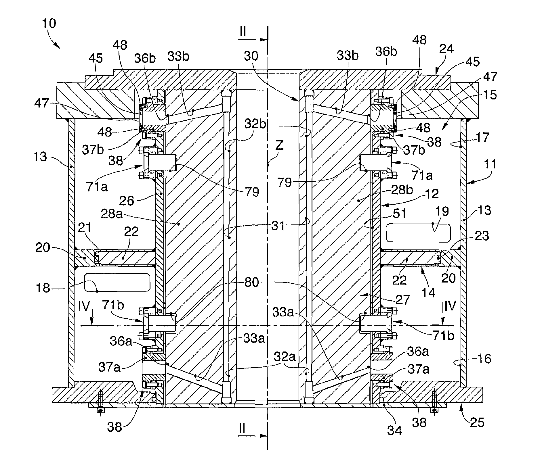
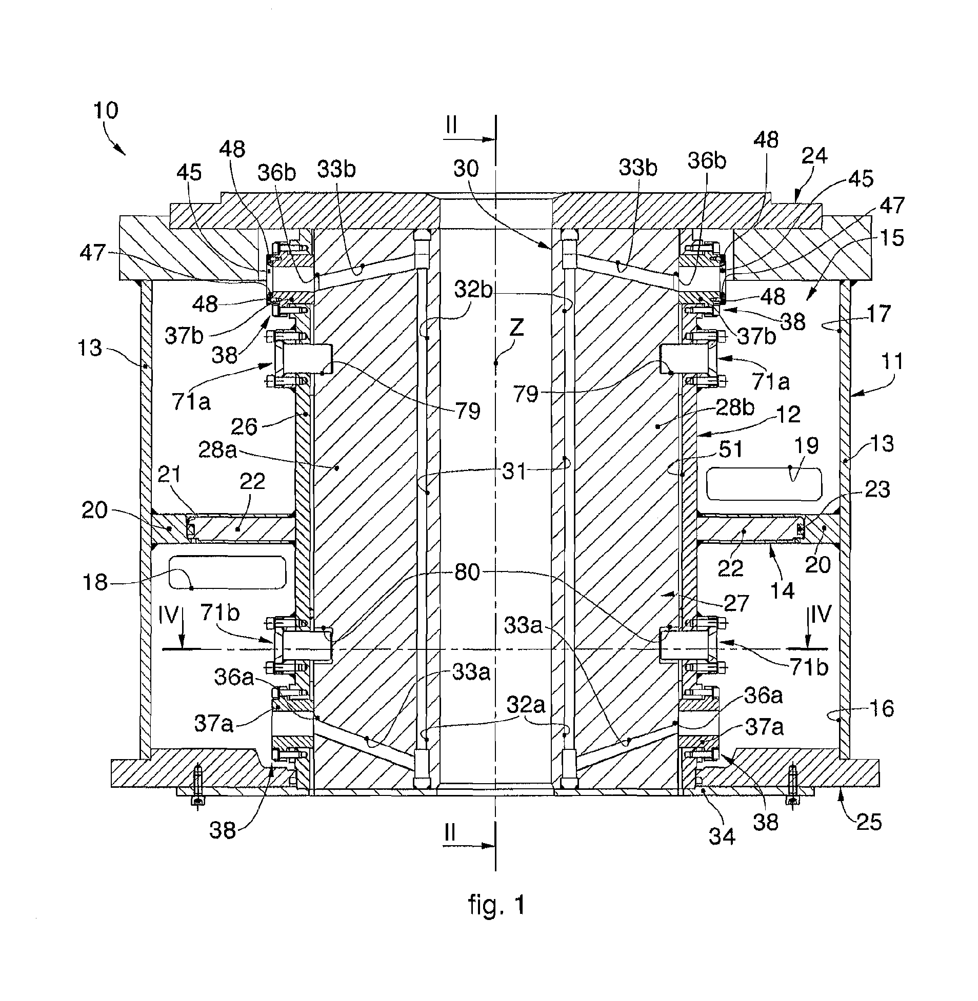
[0063]With reference to FIG. 1 an apparatus for continuous casting is indicated in its entirety by the reference number 10 and comprises a support structure or mold body 11, to which a mold 12 is associated, in this case, of the plate type. The mold body 11 also allows to install molds of the tubular type.

[0064]The mold body 11 is provided with a containing casing 13 in which, during use, the mold 12 is inserted. Between the containing casing 13 and the mold 12 a closed chamber 15 is defined, to contain the cooling water. The containing casing 13 is closed at the top by an upper flange 24 and below by a lower flange 25.

[...


PUM

PropertyMeasurementUnit
Flow rateaaaaaaaaaa

Abstract

Apparatus for continuous casting comprising a support structure provided with a containing casing configured to support inside it a mold equipped with a plurality of longitudinal passage channels for the passage of a cooling liquid. The containing casing and the mold together define an introduction chamber and a discharge chamber for the cooling liquid, and the introduction chamber and the discharge chamber are fluidically connected by the passage channels. The mold comprises a first tubular element and a second tubular element disposed inside the first tubular element. The second tubular element comprises a plurality of plates each provided with passage channels and connected to each other to define a through casting cavity. The first tubular element is provided with connection members to connect the passage channels of the plates respectively with the introduction chamber and with the discharge chamber.

Description

FIELD OF THE INVENTION[0001]The present invention concerns an apparatus for continuous casting that allows to continuously cast metal products such as slabs with a rectangular section and bars with a double “T” section, also known as “beam blanks”.[0002]In particular, the apparatus for continuous casting allows to install both crystallizers of the tubular type and also crystallizers of the plate type.BACKGROUND OF THE INVENTION[0003]An apparatus is known for continuous casting comprising a support structure or framework, defining a closed tubular support body, or body to support and contain the mold, hereinafter indicated as mold body.[0004]The mold body, depending on its particular constructional configuration, can allow to install a mold of the tubular type or plate type.[0005]Molds of the tubular type allow to obtain metal products with very simple and even cross section, for example blooms or billets with a round or square section, or with a more complex cross section but of lim...

Claims


Application Information

Patent Timeline
IPC IPC(8): B22D11/00B22D11/103B22D11/22
CPCB22D11/009B22D11/103B22D11/22B22D11/0406B22D11/041B22D11/055
Inventor COMAND, DANIELEFRANCESCHINIS, ENZO
Owner DANIELI & C OFF MEC SPA
Why Eureka
Try Eureka