

Bracket for clotheshorse
- Summary
- Abstract
- Description
- Claims
- Application Information
AI Technical Summary
Benefits of technology
Problems solved by technology
Method used
Image

Examples
Embodiment Construction
[0022] A bracket for a clotheshorse in accordance with the present invention is used on a clotheshorse in pairs to hold multiple rods, racks, shelves or other accessories between two brackets. The two brackets with the versatile and detachable accessories are called a “bracket assembly” in the following description.
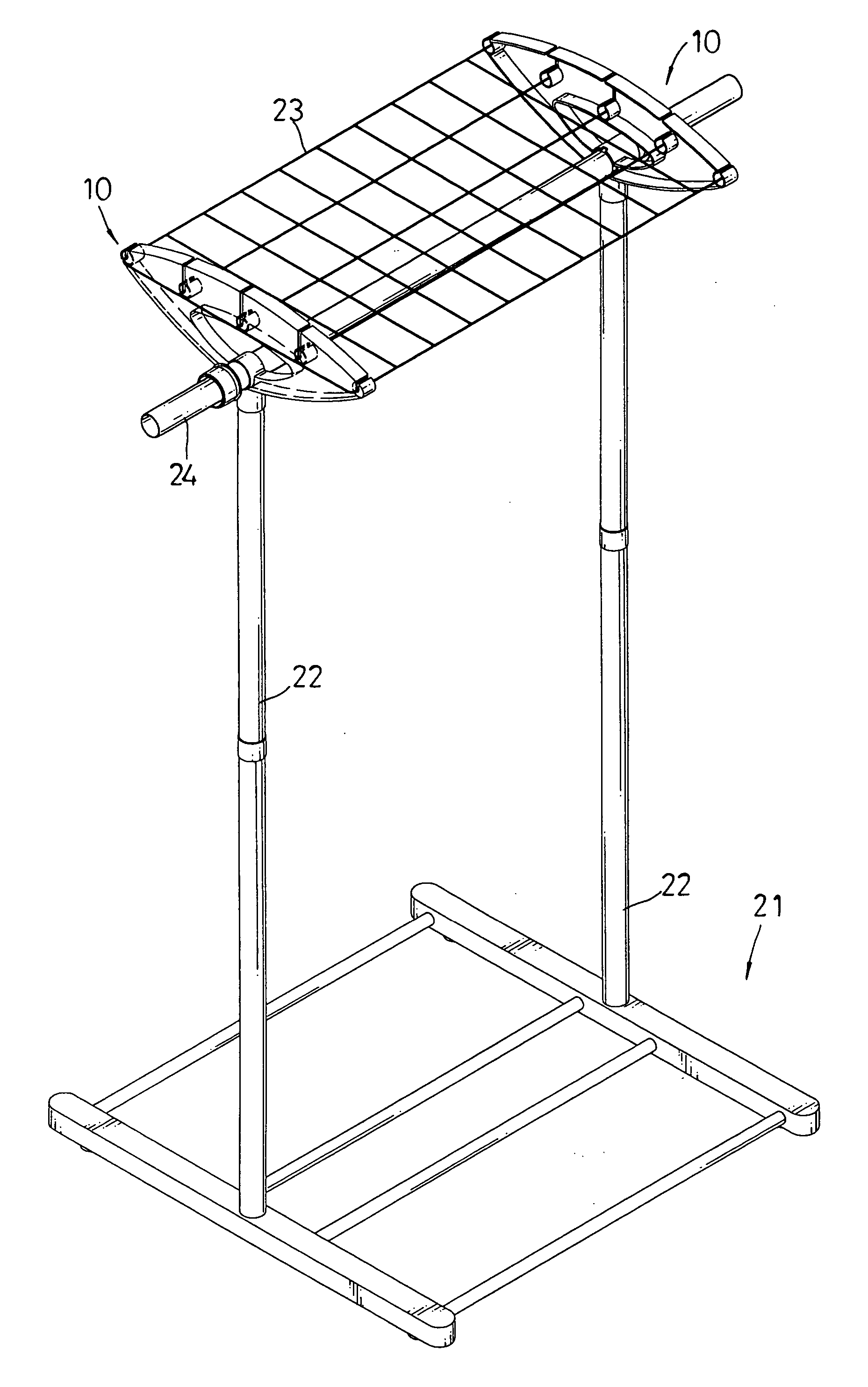
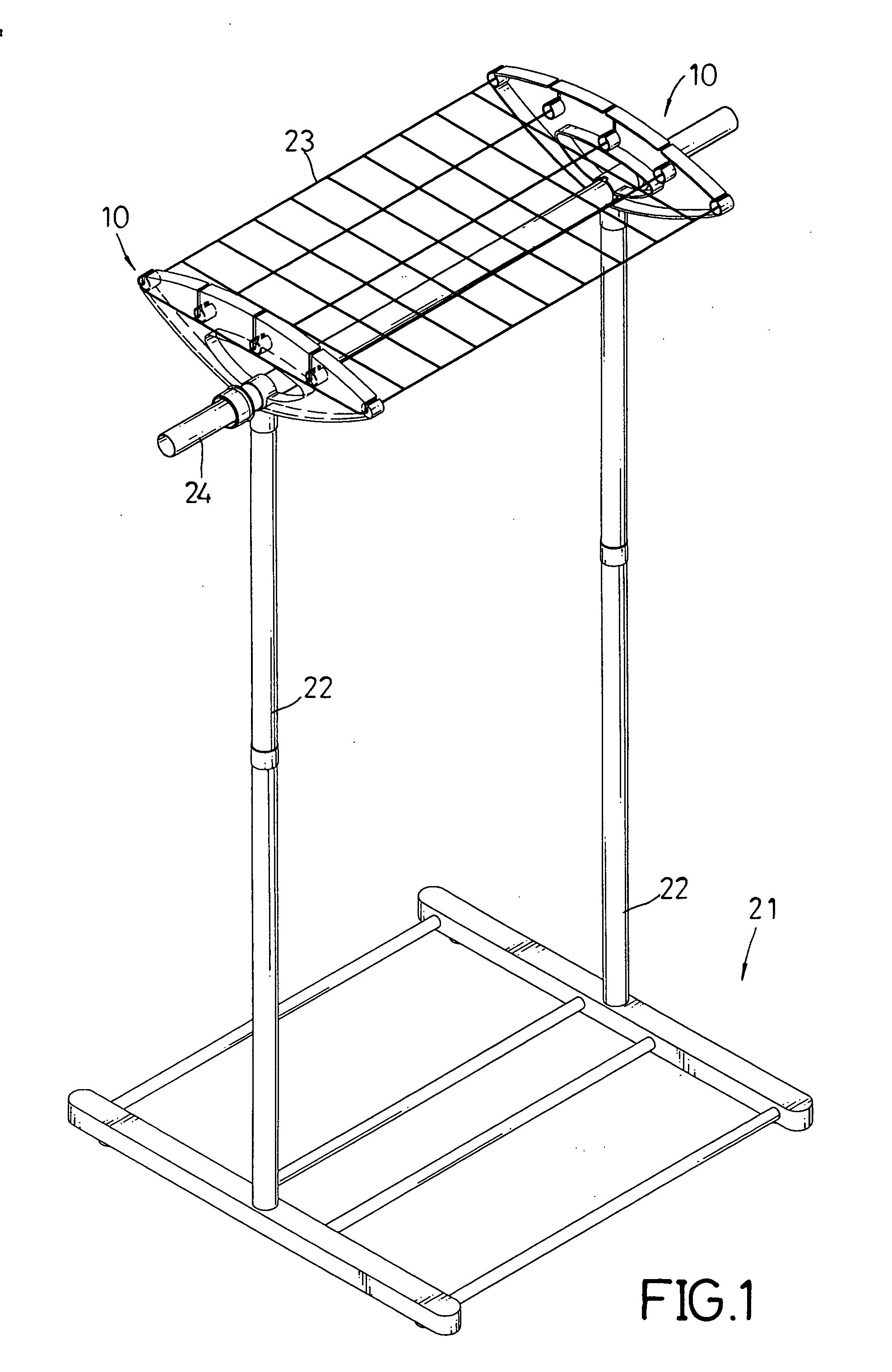
[0023] With reference to FIG. 1, a clotheshorse comprises a base (21), two telescoping rods (22) and a bracket assembly (not numbered). The base (21) is a rectangular frame having two ends (not numbered). The two telescoping rods (22) are mounted respectively on the two ends of the base (21). Each telescoping rod (22) has a distal end (not numbered). The bracket assembly is detachably mounted on the distal ends of the two telescoping rods (22).
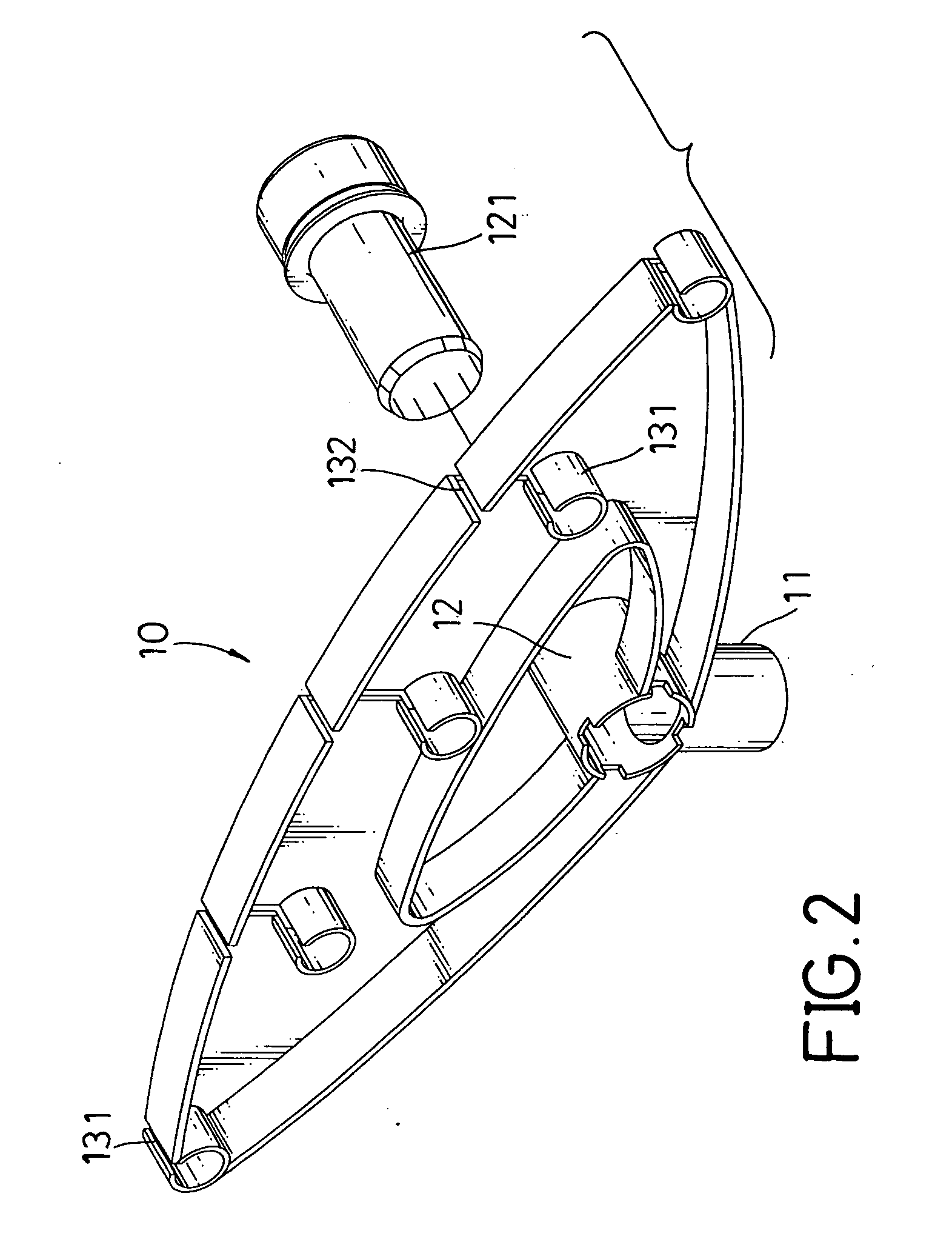
[0024] With further reference to FIGS. 2 and 3, the bracket assembly comprises two brackets (10) in accordance with the present invention, an optional hanging rod (24) and an optional rack (23) composed of multiple transverse and ...
PUM
 Abstract
Description
Claims
Application Information