Contactless sensor unit for a coordinate measuring machine

Pending Publication Date: 2022-06-23
TESA SARL
View PDF0 Cites 0 Cited by
  • Summary
  • Abstract
  • Description
  • Claims
  • Application Information

AI Technical Summary

Benefits of technology

The present invention provides a contactless sensing unit that can accommodate different types of optical probe devices with different sizes and shapes. It allows for precise positioning of the contactless sensing unit. The accurate positioning of the optical probe device provided by the collar allows for optimizations in measurements and calibration processes by reducing the uncertainty caused by the manufacturing and assembly of the optical probe device. The data storage circuit enables automatic or semi-automatic measurements and calibration processes.

Problems solved by technology

However, it lacks in versatility for measuring more complex surfaces.
Increased measurements versatility is counterbalanced by a more complex assembly of the CWS sensing unit as well as an increase of the weight and size of the CWS sensing unit which must be handled by the probe head during measurements.
The above-described CWS measuring systems are not adapted for integrating several optical probe devices having different shapes and / or sizes.
Moreover, integration of the optical probe device in a CWS contactless sensing unit of a CMM machine, as disclosed in WO2009062641 and in EP2667147, may be difficult to achieve as the contactless sensing unit has to be precisely and permanently supported by the CMM in any possible position, not only independently of the orientations and of the movements of the optical probe, but also for a large catalogue of optical probe devices.
An efficient integration of this optical probe device in the CWS contactless sensing unit is therefore costly.
The measurement probe housing is therefore rotatably mounted relative to the probe unit interface which has the inconvenient to provide only a coarse positioning of the measurement probe.

Method used


Image

  • Contactless sensor unit for a coordinate measuring machine
  • Contactless sensor unit for a coordinate measuring machine
  • Contactless sensor unit for a coordinate measuring machine

Examples


Embodiment Construction

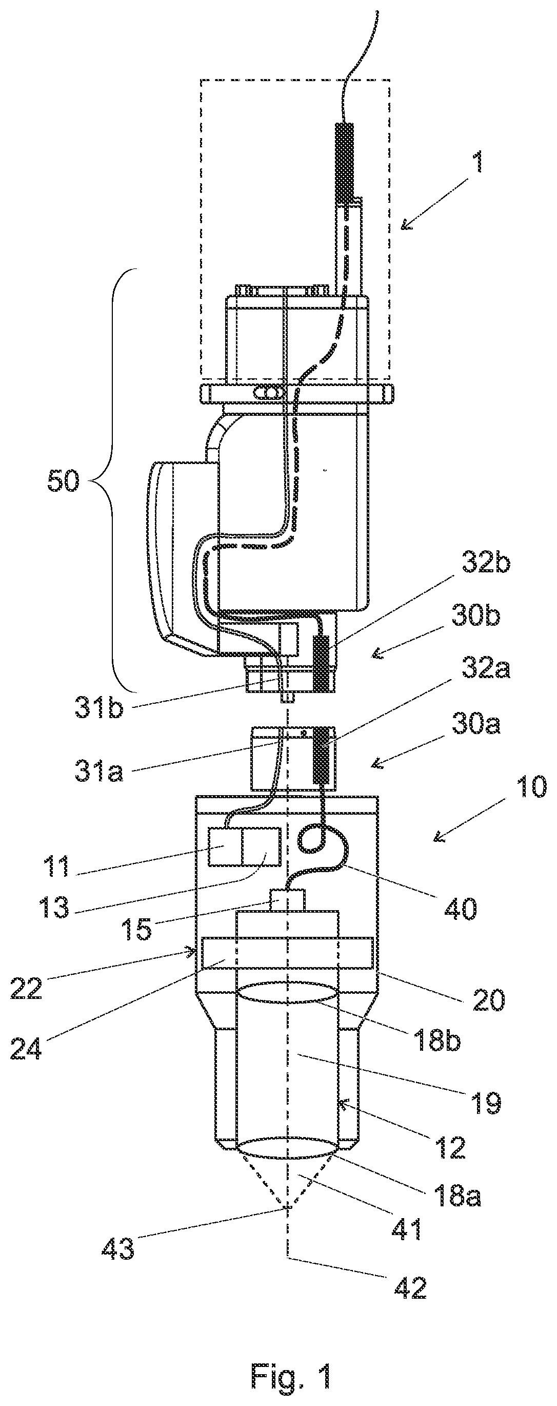
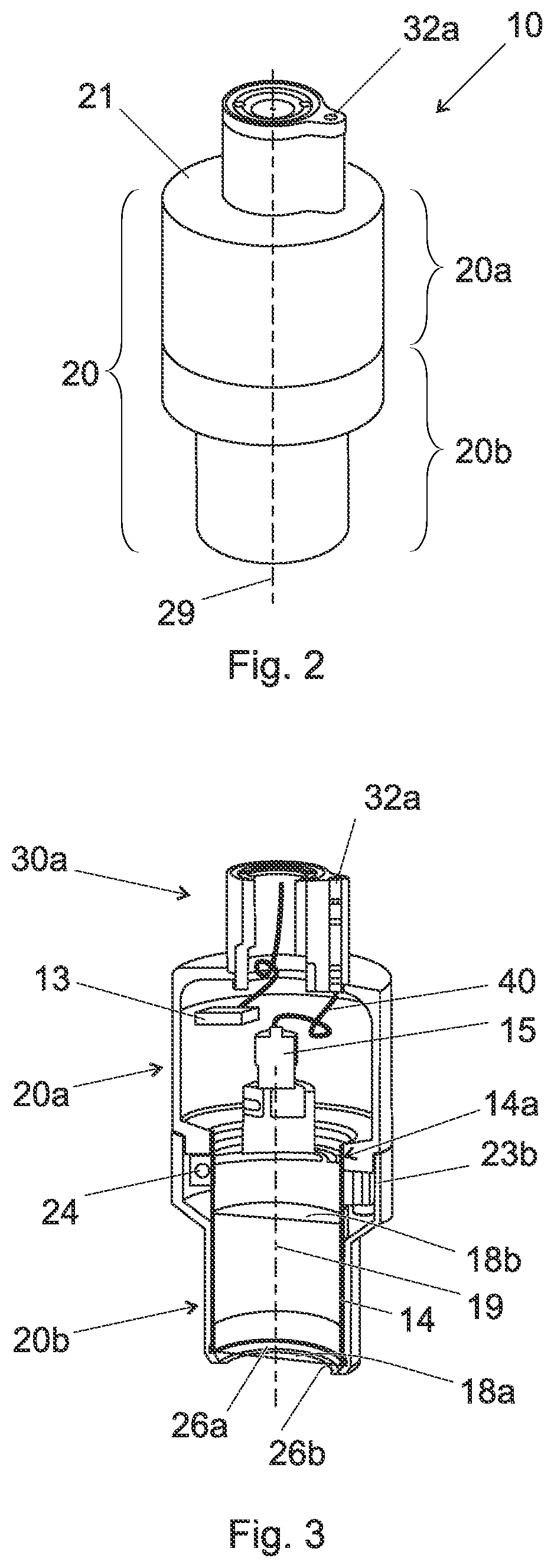
[0047]The invention relates to a contactless sensing unit 10 for a measuring apparatus or machine tool 1 as illustrated in FIG. 1. The contactless sensing unit 10 comprises an optical probe device 12 and a coupling element 30a for mechanical connection to a complementary coupling element 30b on the measuring apparatus or machine tool 1, possibly on an articulated probe head 50 thereof.

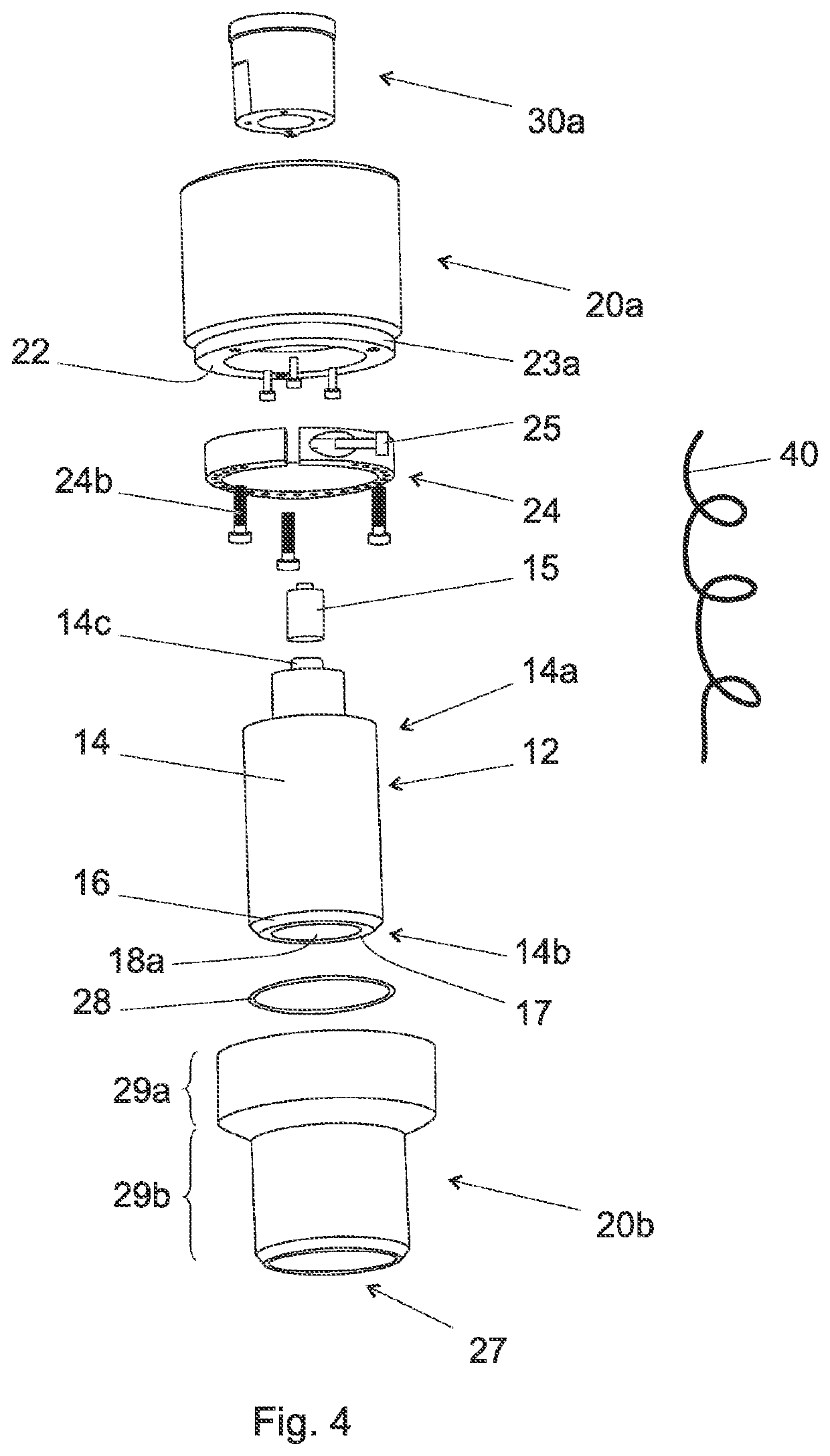
[0048]The optical probe device 12 comprises one or more optical objectives, for example a first and second objectives 18a, 18b for contactless sensing a surface of a workpiece for providing a dimensional or surface properties measurement. The optical probe device 12 can be configured to allow a manual or automatic replacement of the one or more optical objectives 18a, 18b.

[0049]In particular, the optical probe device 12 can be (mechanically) configured, by means of one or more optical objectives 18a, 18b, to emit light (in a predefined manner) against a surface of the workpiece for dimensional or surf...


PUM


Abstract

Disclosed herein is a contactless sensing unit for a measuring apparatus or machine tool 1, notably for a coordinate measuring machine (CMM). The contactless sensing unit comprises an optical probe device, a coupling element for mechanical connection to a complementary coupling element on the measuring apparatus or machine tool and a housing for housing the optical probe device. The housing is mechanically connected to the coupling element. The optical probe device comprises an optical objective at a distal end of a lower portion of the probe device for sensing a surface of a workpiece. The contactless sensing unit further comprises a collar for adjusting a relative axial, radial and / or angular position of the optical probe device with respect to a fastening portion of the housing. The collar circumferentially clamps the optical probe device essentially around an upper portion of the optical probe device.

Description

FIELD OF THE INVENTION[0001]The present invention concerns a contactless sensor unit for measuring apparatus, notably for coordinate measuring machine (CMM), and, alternatively or complementarily, for machine tools, notably for computerized numerical control machines (CNC). The contactless sensor unit may be, in particular, part of a chromatic white light sensing (CWS) system for dimensional and / or surface properties (e.g. roughness) measurements.DESCRIPTION OF RELATED PRIOR ART[0002]A CWS measuring system relies on illuminating a surface to be measured by a white light generated by a light source, for example a polychromatic light source. The CWS measuring system comprises an optical probe device with an optical objective for focusing different wavelengths of this light at different distance from the optical probe device. The surface will then substantially reflect the focused wavelength while dispersing the other wavelengths. The distance between the surface and the optical probe ...

Claims


Application Information

Patent Timeline
IPC IPC(8): G01B11/00
CPCG01B11/005G01B11/007G01B11/026G01B2210/50
Inventor ETTELT, DIRKSINGER, JULIENCHARDONNENS, JULIENMANETTI, DAVIDE
Owner TESA SARL
Why Eureka
Try Eureka