Calibration target for video processing

a technology for video processing and target image, applied in image analysis, image enhancement, instruments, etc., can solve the problems of current imaging calibration system being relatively slow and inaccura

Active Publication Date: 2016-03-31
LUCASFILM ENTERTAINMENT
View PDF0 Cites 27 Cited by
  • Summary
  • Abstract
  • Description
  • Claims
  • Application Information

AI Technical Summary

Problems solved by technology

Current systems for imaging calibration are relatively slow and inaccurate.

Method used


Image

  • Calibration target for video processing
  • Calibration target for video processing
  • Calibration target for video processing

Examples


Embodiment Construction

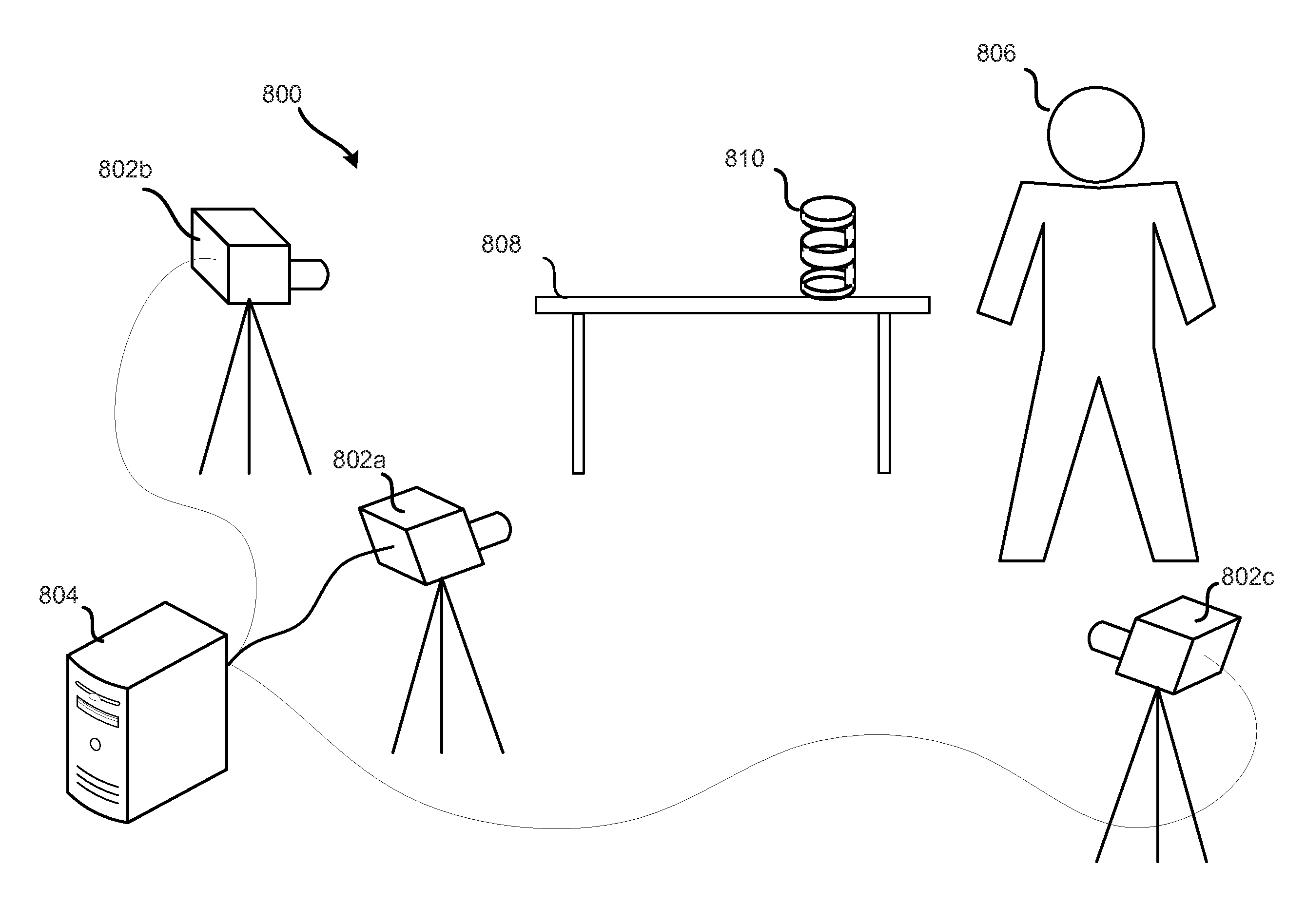
[0020]Embodiments of the invention are directed to devices, methods and systems for automatically calibrating a camera. Calibration of a camera entails, in part, determining parameters of a camera related to its focal length, principal point, and other values that affect how the camera produces a two-dimensional (2D) image from a view of points in a three-dimensional (3D) space. Once known, the parameters of the camera may be used in forming or adjusting the images that the camera produces.

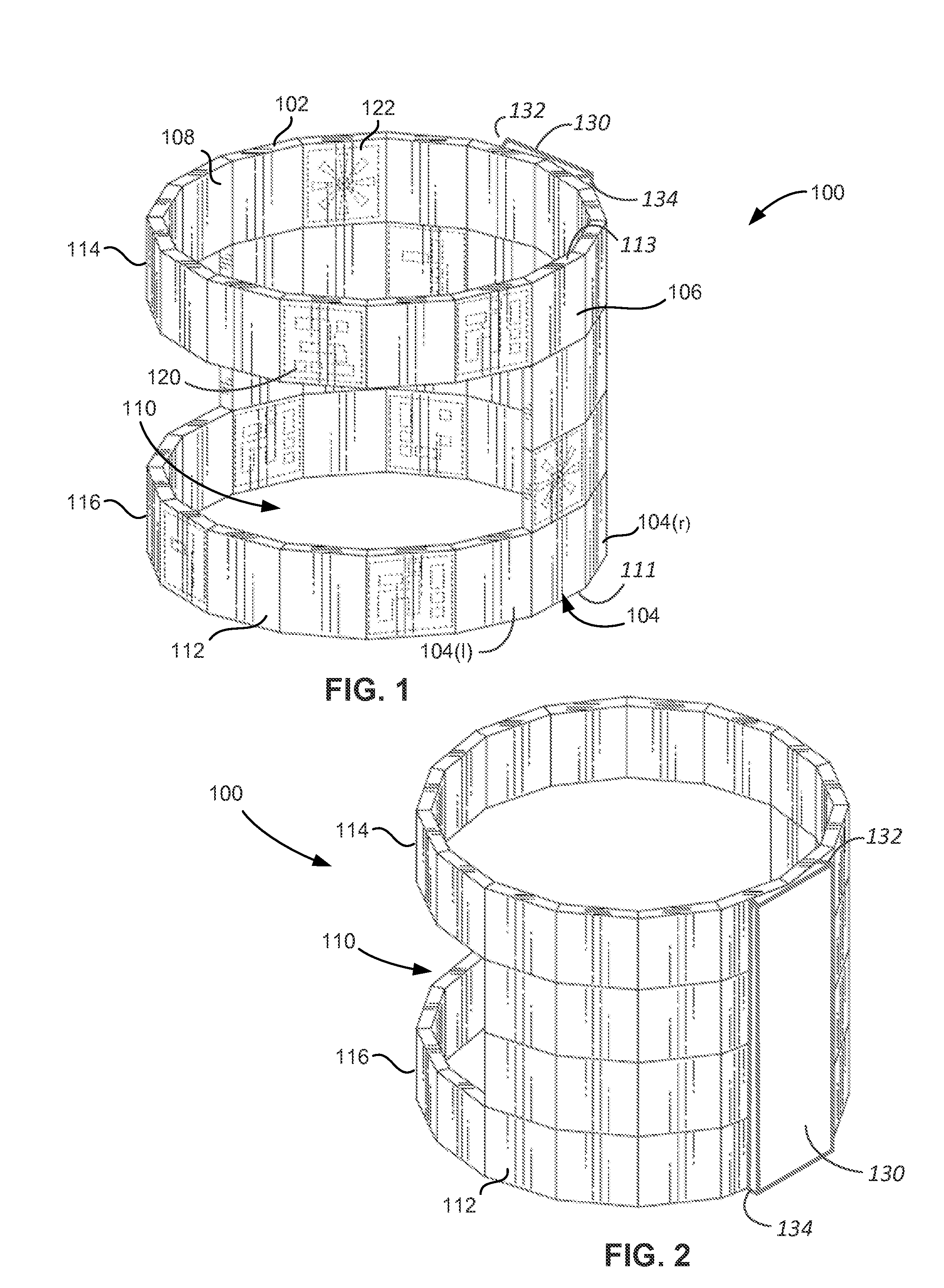
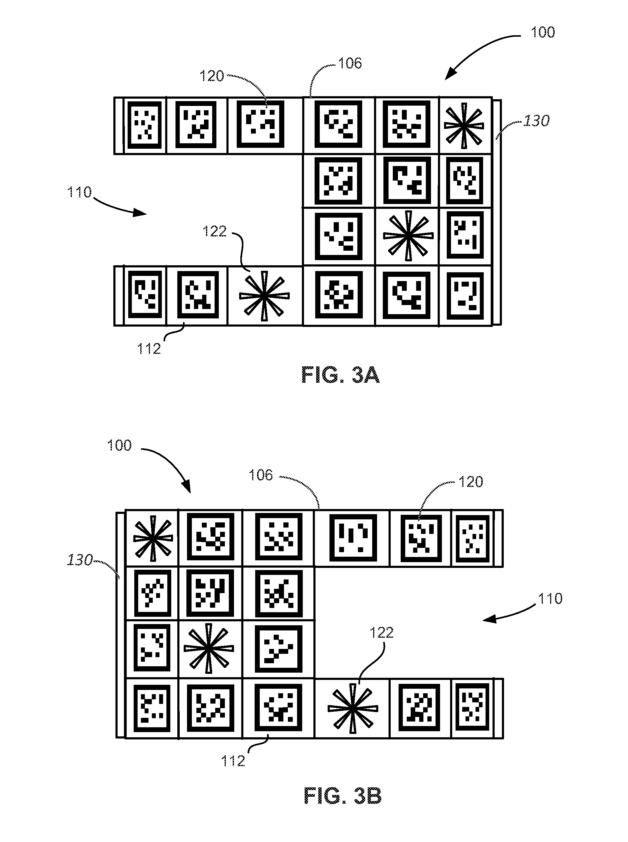
[0021]Often, calibrating a camera involves producing one or more images or pictures of a test object with the camera, locating components of the image that correspond to particular parts of the test object, and calculating the camera parameters based on the image components, the geometry of the test object, its position relative to the camera when the image was taken, and the physical assumptions about the camera. The test object is sometimes referred to as a calibration target or a calibration to...


PUM


Abstract

An apparatus is disclosed which may serve as a target for calibrating a camera. The apparatus includes a hollow body having an interior surface, an exterior surface and at least one window formed in the hollow body through which the interior surface is visible. A plurality of distinguishable fiducial markers are arranged in a predetermined pattern along the interior and exterior surface of the hollow body. The fiducial markers can be distinguishable such that, for any given image of the target captured by a camera, there is only one position, rotation, distortion value, and focal length for the camera of interest.

Description

CROSS-REFERENCES TO RELATED APPLICATIONS[0001]This application is related to commonly assigned U.S. patent application Ser. No. 14 / 248,124, filed on Apr. 8, 2014, and entitled “AUTOMATED CAMERA CALIBRATION METHOD AND SYSTEM,” which is incorporated by reference herein in its entirety.BACKGROUND OF THE INVENTION[0002]A camera creates a record of a three-dimensional (3D) physical scene with a two-dimensional (2D) image. The image may be recorded on a film or as a digital 2D array of pixel values. Computer-based animation techniques often involve capturing a series of images of an actor (or other object) with one or more cameras, which may have different viewing perspectives. The images from these cameras can be combined to generate a three-dimensional (3D) graphical representation of the actor that can be applied to an animated character and placed in a computer-generated 3D scene.[0003]In order for the 3D representation and location of the character in the 3D scene to be accurate, the...

Claims


Application Information

Patent Timeline
Patent Type & Authority Applications(United States)
IPC IPC(8): H04N17/00G06T7/00
CPCG06T7/0018H04N17/002H04N5/2224G06T2207/30204G06T7/80
Inventor WARNER, PAIGE
Owner LUCASFILM ENTERTAINMENT
Why Eureka
Try Eureka